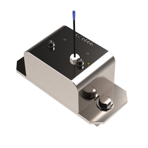
LSI GS010 Crane Angle Sensor Installation
Installation & Users Manual
 Free Quote
(Part of the GS Series Installation Manuals)
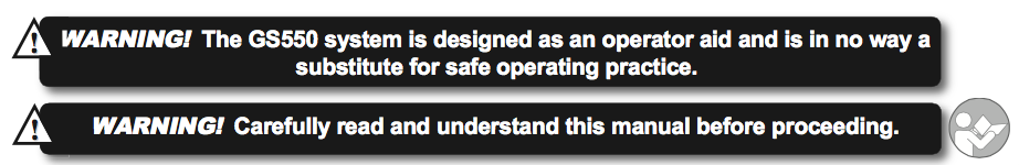
Before proceeding read and understand the following:
For your safety and that of the people that come into contact with LSI products, understand the significance of the instructions included in this guide, respect all laws and regulations and comply with applicable standards. Pay particular attention to items bearing the alert symbol:
![]() 

and the following words:
![]()
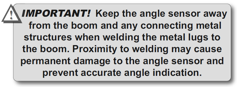
Important: this denotes an instruction that if not complied with may lead to product performance issues.

2.3 Crane Angle Sensor for the Boom or Jib
2.3a Mounting Procedure
When starting the LSI GS010 crane angle sensor installation the GS010 series angle sensors can be turned on by starting up the GS550 display to which they are programmed. The angle sensor can then assist in levelling itself with the red and green LED.
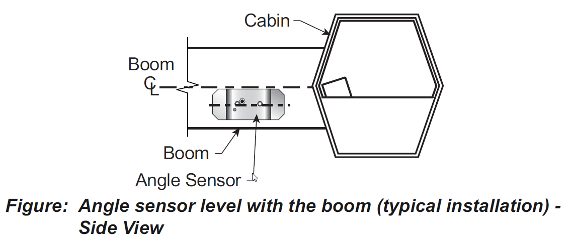
1. Determine the angle sensor position.
a. The GS010-01 boom angle sensor can be mounted on either side of the boom.
b. The GS010-02 360° angle sensor must be mounted on the port side of the jib.
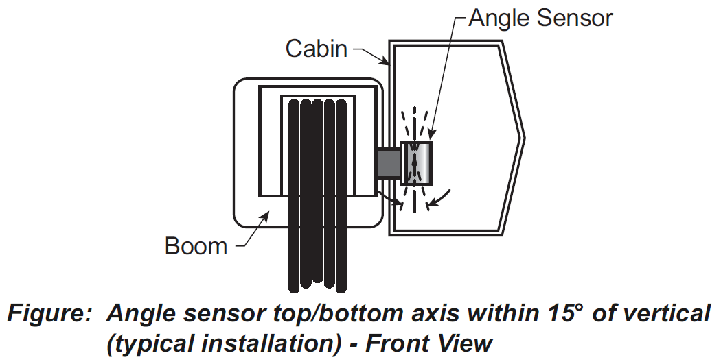
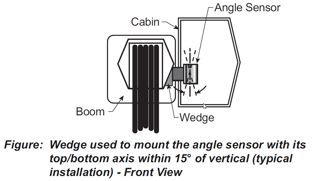
c. The angle sensor must be level with the boom or jib centerline.
d. The top / bottom axis of the angle sensor must be within 15 degrees of vertical
e. The angle sensor should have a clear line of sight to the cabin mounted display.
f. The angle sensor antenna should not contact a metal object.
2. Install the welding pads; keep the angle sensor at least three feet from the weld site and any connecting metal objects while welding.
3. Mount the angle sensor to the weld pads with the screws and washers provided.
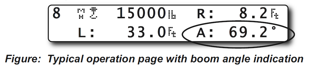
4. Verify angle indication on the GS550 LCD.
5. If the angle displayed by a GS010-01 boom angle sensor is a high negative value, then tilt the angle sensor up over 45 degrees, and then tilt back down to horizontal. The GS010-01 boom angle sensor will automatically detect on which side of the boom it is installed and correct angle indication accordingly.
2.3b Angle Calibration Procedure
№ 1: Mechanical Set-Up
1.Level the boom such that it is perfectly horizontal; use a high quality bubble or digital angle sensor. If the GS550 display indicates 0.0 degrees then angle calibration is complete; if not then continue to step 2.

2. For GS011 angle/length sensors only: Carefully remove the cover of the GS101 cable reel.
3. Loosen the mounting screw in the slotted hole of the angle sensor mounting plate.
4. Pivot the angle sensor slightly until angle indication is correct. Repeat the angle validation (step 1) as required.
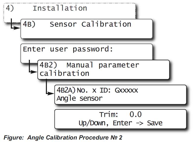
2.3c Angle Calibration Procedure
№ 2: Correct with the GS550
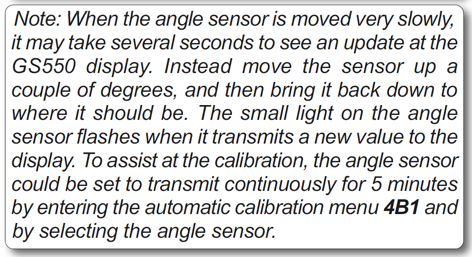
Calibrate angle indication by adjusting the trim (offset) value in the GS550 display; the GS550 will then communicate the updated trim value to the sensor.
1. Position the boom at a precisely known angle.
2. Go to 4B) SENSOR CALIBRATION and press Enter.
3. Enter the user password (using Back, Next, Up and Down as described in Password settings section) and press Enter.
4. Go to 4B2A)
5. Use Back and Next to select the angle sensor to be calibrated.
6. Press Enter and then Next to go to the trim adjustment page.
7. Use Up and Down to adjust the trim value.
Example: If angle indicated is 0.3° over the actual angle, adjust the trim value to -0.3.
Example: If angle indicated is 0.9° below the actual angle, adjust the trim value to 0.9.
8. Press Enter to save changes.
9. Press Exit four times to return to the operation display.
10.Verify accurate angle indication at both very high and very low angles.
(OR USE INDEX TO CLICK ON SECTION NEEDED)
1.1 OVERVIEW
1.2 START-UP
2.1 DISPLAY GS550
2.1a Mounting Bracket
2.1b Antenna Position
2.1c Power Supply and Lockout Connection
2.1d Lockout Settings
2.1e Password Settings
2.3 ANGLE SENSORS FOR THE BOOM OR JIB
2.3a Mounting Procedure
2.3b Angle Calibration Procedure No 1: Mechanical Set-Up
2.3c Angle Calibration Procedure No 2: Correct with the GS550
2.4a Switch Bracket Installation LB011
2.4b GS050 Installation
2.4c GS075B Installation
2.4d Chain length adjustment
2.5a Maximum Boom Extension
2.5b Mounting the Cable Reel
2.5c Boom Length Calibration Procedure No 1: Mechanical Set-Up
2.5d Boom Length Calibration Procedure No 2: Correct with the GS550
2.6a Radius Verification and Adjustment
2.6b Radius Settings
2.6c Basic Radius Parameters for a Lattice Crane
2.6d Basic Radius Parameters for a Telescopic Boom Crane
2.6e Advanced Radius Parameters
2.7 WIRELESS WIND SPEED SENSOR GS020
2.8 WIRELESS LOAD PINS
2.8a LP011, LP015, and LP026
2.8b Load Pin Transmitter GS001
2.9 LINE RIDING TENSIOMETER
2.9a Line Riding Tensiometer Installation
2.9b Line riding tensiometer installation on a swing arm
2.10 LOAD PINS, LINE RIDING TENSIOMETERS AND COMPRESSION CELLS: CALIBRATION
2.11 FOUR POINT LIFT
2.11a Sum Load Indication
2.11b Imbalance
2.11c Slack Rope
2.12 LIST AND TRIM ANGLE SENSOR
2.12a Programming the GS550 for List and Trim Indication
2.12b Mounting Instructions
2.12c List and Trim Angle Calibration Procedure
2.13 ROPE PAYOUT
2.13a Rope Payout Calibration Procedure No 1: Mechanical Set-Up
2.13b Rope Payout Calibration Procedure No 2: Correct with the GS550
2.13c Rope Payout Limits
2.13d Electrical connections
2.14 SLEW SENSOR INSTALLATION
2.14a Encoder Gear Verification
2.14b Slew Encoder Location
2.14c Slew Encoder Orientation
2.14d Slew Encoder Installation
2.14e Slew Transmitter Location
2.14f Slew Transmitter Installation
2.14g Cable Length Adjustment
2.15 SLEW SENSOR CALIBRATION
2.16 DATALOGGER
2.16a Recording Modes
2.16b Date and Time
2.17 SENSOR LIST
2.17a How to Add a Sensor to the GS550
2.17b How to Remove a Sensor from the GS550
2.18 NETWORK OPTIONS
2.18a Listen Only Mode
2.18b Repeater
2.18c Wireless Sensor Update
3. OPERATION
3.1 DISPLAY GS550
3.2 USB PORT
3.3 KEYPAD
3.3a Tare
3.3b Info
3.3c Limit
3.4 DISPLAY ABBREVIATIONS
3.5 SYSTEM MENU
3.5a Menu Numbers
3.5b Menu Navigation
3.5c Password Protection
3.5d Menu Layout
3.5e Parts of Line
3.6 RATED CAPACITY INDICATORS
3.6a Display Programming
3.6b Crane Rigging
3.6c Chart Wizard
3.7 DISPLAY SETTINGS
3.7a Weight Units
3.7b Wind Units
3.7c Language
3.7d Light Intensity
3.7e Contrast
3.7f Backlight Mode
3.8 SYSTEM DIAGNOSTIC
3.8a System Sensors Diagnostic
3.8b Radio Network Diagnostic
3.8c Lockout Diagnostic
3.8d Display Diagnostic
3.8e Digital Input Diagnostic
3.9 WORK AREA MANAGEMENT
3.9a Set Fixed Limits
3.9b Set Dynamic Limits
3.9c Clear all work area limits
3.9d Warning, alarm and lockout
3.9e Slew and work area display
4. USB TOOL
4.1 DATA LOGGER TRANSFER FROM DISPLAY
4.1a Transfer from display to USB device
4.1b Transfer from USB device to PC
4.1c Troubleshooting
4.2 UPLOAD CAPACITY CHARTS
4.3 DATA LOGGER VIEWER
4.3a Installation on a PC
4.3b Quick Start
4.3c Full Report
4.3d Wind Report
5. MAINTENANCE
5.1 SENSORS
5.1a Replacing Sensor Battery
5.2 ANTI-TWO-BLOCK SWITCH
5.2a Replacing the GS050 Batteries
5.2b Replacing the GS075B Battery
5.3 REPLACING A SENSOR ANTENNA
5.4 LOAD CELLS
5.4a Reading Accuracy
5.4b Load Testing
5.4c Care
6. TROUBLESHOOTING
7. CERTIFICATION NOTES
7.1 MODEL NUMBERS
7.2 IMPORTANT NOTES FOR HAZARDOUS AREA CERTIFIED COMPONENTS
7.2a Specifications
7.2b Ensuring Safe Operation in Hazardous Areas
7.2c Product Repair And Servicing
7.3 EQUIPMENT MARKINGS
7.4 GS550 DISPLAY LABELS
7.5 CLASS 1 DIVISION 1 AND DIVISION 2 CERTIFICATIONS
7.6 ATEX CERTIFICATIONS
7.7 FCC AND IC – INSTRUCTIONS TO THE USER
7.8 EMI / EMC
7.9 ENVIRONMENTAL CONDITIONS
7.10 CE
7.10a Declaration of conformity
7.10b CE Safety
8. GS550 MENU OUTLINE
9. LSI PRODUCT LIMITED WARRANTY – 2009/02/16
9.1 LIMITED WARRANTY
9.2 WARRANTYSERVICES PROCEDURES
9.3 EXCLUSION OF OTHER WARRANTIES
9.4 EXCLUSION
9.5 LIMITATION OF LIABILITY
9.6 RECOMMENDED PRACTICES
9.7 CHOICE OF LAW
9.7a Entire Agreement


