LSI GS Wireless Load Cell Installation
Installation & Users Manual
 Free Quote
(Part of the GS Series Installation Manuals)
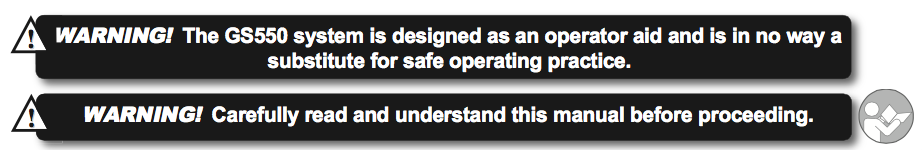
Before proceeding read and understand the following:
For your safety and that of the people that come into contact with LSI products, understand the significance of the instructions included in this guide, respect all laws and regulations and comply with applicable standards. Pay particular attention to items bearing the alert symbol:
![]() 

and the following words:
![]()
Important: this denotes an instruction that if not complied with may lead to product performance issues.
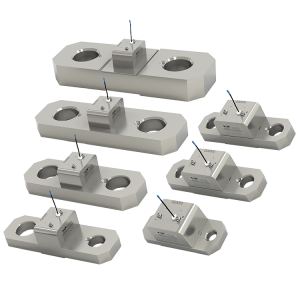
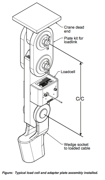
2.2 LSI GS Wireless Load Cell Installation
1. To begin the LSI GS wireless load cell installation install load cell bushings as supplied by LSI. Assembly of the load cell and adapter plates must be configured to the pin size required by the specific dead end or hook to which it is to be attached. In all cases, the bushings supplied by LSI must be used where possible to adapt the holes in the load cell to the pins. Bushings must be secured with the two allen screws provided, one on each side of the load cell.
2. As required, place a washer between adapter plate and pin head or nut on each end of the pin that links the adapter plates to the load cell. Additional washers should be added equally to each end of the pin as required to inhibit excessive lateral movement of load cell (maximum 1/8” total movement) and adapter plates along the pin.
3. If the dead end or hook to be connected to the adapter plates requires a larger opening, washers may be placed between the load cell and the adapter plates equally on both sides of the load cell.
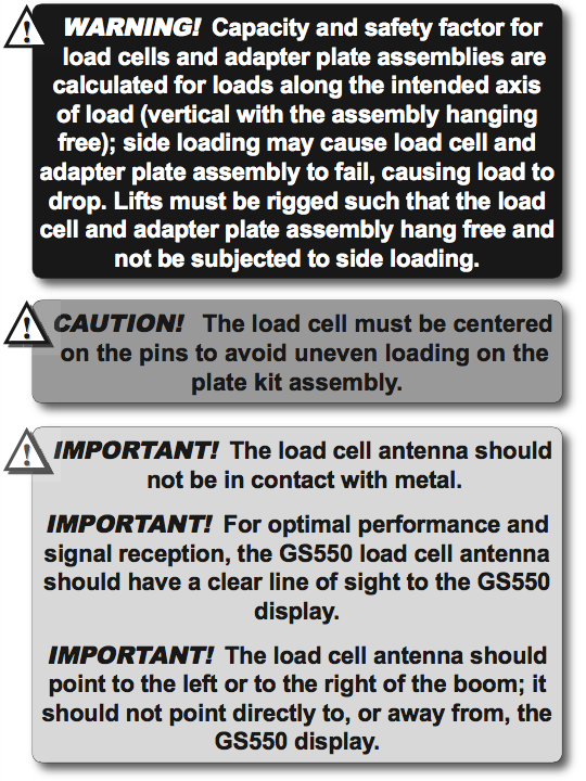
4. In all cases the washers must be placed symmetrically such that the load cell is centered on the pins to avoid uneven loading
5. Secure the pins with the nuts and cotter pins provided.
6. A qualified (lift supervisor or crane inspector) person must verify every lift assembly before first use and periodically thereafter (one to twelve months), including before any new, difficult or otherwise different lift.
(OR USE INDEX TO CLICK ON SECTION NEEDED)
1.1 OVERVIEW
1.2 START-UP
2.1 DISPLAY GS550
2.1a Mounting Bracket
2.1b Antenna Position
2.1c Power Supply and Lockout Connection
2.1d Lockout Settings
2.1e Password Settings
2.3 ANGLE SENSORS FOR THE BOOM OR JIB
2.3a Mounting Procedure
2.3b Angle Calibration Procedure No 1: Mechanical Set-Up
2.3c Angle Calibration Procedure No 2: Correct with the GS550
2.4a Switch Bracket Installation LB011
2.4b GS050 Installation
2.4c GS075B Installation
2.4d Chain length adjustment
2.5a Maximum Boom Extension
2.5b Mounting the Cable Reel
2.5c Boom Length Calibration Procedure No 1: Mechanical Set-Up
2.5d Boom Length Calibration Procedure No 2: Correct with the GS550
2.6a Radius Verification and Adjustment
2.6b Radius Settings
2.6c Basic Radius Parameters for a Lattice Crane
2.6d Basic Radius Parameters for a Telescopic Boom Crane
2.6e Advanced Radius Parameters
2.7 WIRELESS WIND SPEED SENSOR GS020
2.8 WIRELESS LOAD PINS
2.8a LP011, LP015, and LP026
2.8b Load Pin Transmitter GS001
2.9 LINE RIDING TENSIOMETER
2.9a Line Riding Tensiometer Installation
2.9b Line riding tensiometer installation on a swing arm
2.10 LOAD PINS, LINE RIDING TENSIOMETERS AND COMPRESSION CELLS: CALIBRATION
2.11 FOUR POINT LIFT
2.11a Sum Load Indication
2.11b Imbalance
2.11c Slack Rope
2.12 LIST AND TRIM ANGLE SENSOR
2.12a Programming the GS550 for List and Trim Indication
2.12b Mounting Instructions
2.12c List and Trim Angle Calibration Procedure
2.13 ROPE PAYOUT
2.13a Rope Payout Calibration Procedure No 1: Mechanical Set-Up
2.13b Rope Payout Calibration Procedure No 2: Correct with the GS550
2.13c Rope Payout Limits
2.13d Electrical connections
2.14 SLEW SENSOR INSTALLATION
2.14a Encoder Gear Verification
2.14b Slew Encoder Location
2.14c Slew Encoder Orientation
2.14d Slew Encoder Installation
2.14e Slew Transmitter Location
2.14f Slew Transmitter Installation
2.14g Cable Length Adjustment
2.15 SLEW SENSOR CALIBRATION
2.16 DATALOGGER
2.16a Recording Modes
2.16b Date and Time
2.17 SENSOR LIST
2.17a How to Add a Sensor to the GS550
2.17b How to Remove a Sensor from the GS550
2.18 NETWORK OPTIONS
2.18a Listen Only Mode
2.18b Repeater
2.18c Wireless Sensor Update
3. OPERATION
3.1 DISPLAY GS550
3.2 USB PORT
3.3 KEYPAD
3.3a Tare
3.3b Info
3.3c Limit
3.4 DISPLAY ABBREVIATIONS
3.5 SYSTEM MENU
3.5a Menu Numbers
3.5b Menu Navigation
3.5c Password Protection
3.5d Menu Layout
3.5e Parts of Line
3.6 RATED CAPACITY INDICATORS
3.6a Display Programming
3.6b Crane Rigging
3.6c Chart Wizard
3.7 DISPLAY SETTINGS
3.7a Weight Units
3.7b Wind Units
3.7c Language
3.7d Light Intensity
3.7e Contrast
3.7f Backlight Mode
3.8 SYSTEM DIAGNOSTIC
3.8a System Sensors Diagnostic
3.8b Radio Network Diagnostic
3.8c Lockout Diagnostic
3.8d Display Diagnostic
3.8e Digital Input Diagnostic
3.9 WORK AREA MANAGEMENT
3.9a Set Fixed Limits
3.9b Set Dynamic Limits
3.9c Clear all work area limits
3.9d Warning, alarm and lockout
3.9e Slew and work area display
4. USB TOOL
4.1 DATA LOGGER TRANSFER FROM DISPLAY
4.1a Transfer from display to USB device
4.1b Transfer from USB device to PC
4.1c Troubleshooting
4.2 UPLOAD CAPACITY CHARTS
4.3 DATA LOGGER VIEWER
4.3a Installation on a PC
4.3b Quick Start
4.3c Full Report
4.3d Wind Report
5. MAINTENANCE
5.1 SENSORS
5.1a Replacing Sensor Battery
5.2 ANTI-TWO-BLOCK SWITCH
5.2a Replacing the GS050 Batteries
5.2b Replacing the GS075B Battery
5.3 REPLACING A SENSOR ANTENNA
5.4 LOAD CELLS
5.4a Reading Accuracy
5.4b Load Testing
5.4c Care
6. TROUBLESHOOTING
7. CERTIFICATION NOTES
7.1 MODEL NUMBERS
7.2 IMPORTANT NOTES FOR HAZARDOUS AREA CERTIFIED COMPONENTS
7.2a Specifications
7.2b Ensuring Safe Operation in Hazardous Areas
7.2c Product Repair And Servicing
7.3 EQUIPMENT MARKINGS
7.4 GS550 DISPLAY LABELS
7.5 CLASS 1 DIVISION 1 AND DIVISION 2 CERTIFICATIONS
7.6 ATEX CERTIFICATIONS
7.7 FCC AND IC – INSTRUCTIONS TO THE USER
7.8 EMI / EMC
7.9 ENVIRONMENTAL CONDITIONS
7.10 CE
7.10a Declaration of conformity
7.10b CE Safety
8. GS550 MENU OUTLINE
9. LSI PRODUCT LIMITED WARRANTY – 2009/02/16
9.1 LIMITED WARRANTY
9.2 WARRANTYSERVICES PROCEDURES
9.3 EXCLUSION OF OTHER WARRANTIES
9.4 EXCLUSION
9.5 LIMITATION OF LIABILITY
9.6 RECOMMENDED PRACTICES
9.7 CHOICE OF LAW
9.7a Entire Agreement


