LSI GS Cable Reel Length Sensor Installation
Installation & Users Manual
(Part of the GS Series Installation Manuals)
Before proceeding read and understand the following:
For your safety and that of the people that come into contact with LSI products, understand the significance of the instructions included in this guide, respect all laws and regulations and comply with applicable standards. Pay particular attention to items bearing the alert symbol:
![]() 

and the following words:
![]()
Important: this denotes an instruction that if not complied with may lead to product performance issues.
2.5 LSI GS Cable Reel Length Sensor Installation
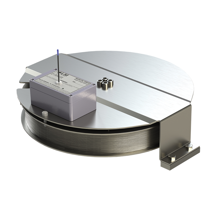
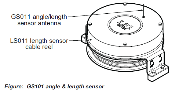
The LSI GS cable reel length sensor includes the GS112 cable reel and the GS011 angle/length sensor. The GS011 is concealed under the cover of the GS112, though the antenna is visible. Following cable reel installation and boom length indication calibration, boom angle indication will have to be verified and possibly calibrated. Refer to Angle Calibration Procedure № 1: Mechanical Set-Up and Angle Calibration Procedure № 2: Correct with the GS550, sections of this manual.
2.5a Maximum Boom Extension
Confirm the maximum extension of the LS101 cable reel is compatible with the maximum boom length.
Step 1. Note the cable reel maximum extension: 100 feet (30.5 metres) unless specified otherwise.
T = ____________________
Step 2. Note the retracted boom length.
A = ____________________
Step 3. Note the maximum extended boom length, not including jib.
B = ____________________
Step 4. Calculate maximum boom extension.
C = B – A = ____________________
Step 5. Compare cable reel maximum extension (T) to maximum boom extension (C).
D = T – C = ____________________
Maximum cable reel extension must be greater than maximum boom extension.
2.5b Mounting the LSI GS Cable Reel Length Sensor
1. Determine placement of the LSI GS cable reel length sensor. Find a clear mounting position on the left side of the first (main) section of the boom. The mounting position should be close to the base of the boom; at least ten feet (three metres) from the tip of the first section and where the cable reel won’t obstruct free boom movement at all boom angles and slew (swing) positions. Furthermore, the reel must be placed such that the cable has a clear straight line to the end of the last section at all boom lengths.
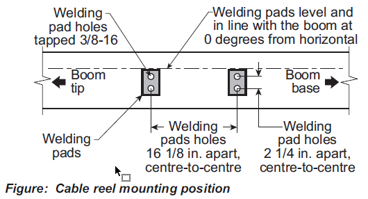
2. Mount the welding tabs. They must be placed parallel to each other, with 16 1/8” inches between the holes’ centres. Install the tabs such that they create a level mounting position in line with the boom at 0 degrees.
3. Attach the LSI GS cable reel length sensor to the welding tabs with the bolts provided.
4. Install the first cable guide (PA111) about 10 feet (3 metres) from the cable reel. Correct alignment of the first guide is critical to ensure orderly winding of the cable on the reel. Install the other guides at the end of each of the intermediate sections and the anchor (PA113) at the end of the last section. All guides must be aligned so as to permit unobstructed movement of the cable.
5. Pull out at least 5 feet (1-1/2 metres) of cable, but not more than half the excess extension of measurement D. Feed through the cable guides and attach to the cable anchor on the tip of the last boom section. If additional cable length is required to reach the cable anchor point remove winds from the reel without putting additional tension on the cable reel spring. There should be minimal tension on the cable reel spring when the boom is fully retracted.
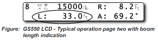
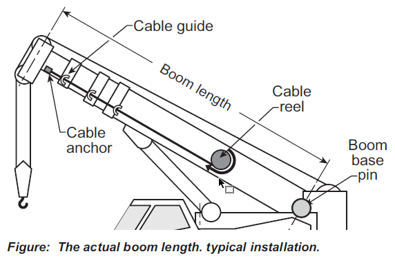
6. Verify the boom length indicated on the GS550 LCD. Boom length is indicated following the length abbreviation “L”, typically on the first or second display operation page. Boom length indicated should equal the actual total boom length. The actual boom length is the distance from the boom base pin to the head sheave centre as measured along the boom centreline. Depending on the exact placement of the cable reel and the cable anchor the displayed length may differ from the actual length.
2.5c LSI GS Cable Reel Length Sensor, Boom Length Calibration Procedure № 1: Mechanical Set-Up
1. Fully retract the boom
2. Adjust the loose wire rope at the boom tip so that the displayed boom length matches the actual boom length.
3. Fully extend the boom
4. Verify the boom length indicated at full boom extension matches the actual fully extended boom length. If not then follow LSI GS Cable Reel Length Sensor Boom Length Calibration Procedure № 2: Correct with the GS550.
2.5d LSI GS Cable Reel Length Sensor, Boom Length Calibration Procedure № 2: Correct with the GS550
If the displayed boom length does not match the actual length of the boom retracted or extended and if it is not possible to easily correct by following 2.6c Boom Length Calibration Procedure № 1, then follow this procedure. This procedure is completed in the operators cab, it requires fully retracting, and then fully extending the boom, as prompted by the on screen instructions.
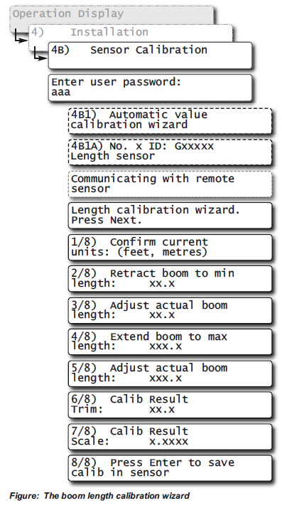
1. Go to menu 4B) SENSOR CALIBRATION.
2. Press Enter to go to the password page.
3. Enter the user password and press Enter twice to go to menu 4B1A).
4. Use Back and Next to select the length sensor, and then press Enter to confirm communication with the sensor is possible.
5. Press Next to start the wizard.
6. Note the units that will be used during the calibration wizard, and then press Next.
7. Fully retract the boom, and then press Next.
8. Use Up and Down to adjust the length value displayed to equal the actual fully retracted boom length, and then press Next.
9. Fully extend the boom, and then press Next.
10.Use Up and Down to adjust the length value displayed to equal the actual fully extended boom length, and then press Next.
11. Note the new trim value, and then press Next.
12.Note the new scale value, and then press Next.
13.Press Enter to send the new calibration to the length sensor.
14.Press Exit three times to return to the operation display.
 Free Quote
(OR USE INDEX TO CLICK ON SECTION NEEDED)
1.1 OVERVIEW
1.2 START-UP
2.1 DISPLAY GS550
2.1a Mounting Bracket
2.1b Antenna Position
2.1c Power Supply and Lockout Connection
2.1d Lockout Settings
2.1e Password Settings
2.3 ANGLE SENSORS FOR THE BOOM OR JIB
2.3a Mounting Procedure
2.3b Angle Calibration Procedure No 1: Mechanical Set-Up
2.3c Angle Calibration Procedure No 2: Correct with the GS550
2.4a Switch Bracket Installation LB011
2.4b GS050 Installation
2.4c GS075B Installation
2.4d Chain length adjustment
2.5a Maximum Boom Extension
2.5b Mounting the Cable Reel
2.5c Boom Length Calibration Procedure No 1: Mechanical Set-Up
2.5d Boom Length Calibration Procedure No 2: Correct with the GS550
2.6a Radius Verification and Adjustment
2.6b Radius Settings
2.6c Basic Radius Parameters for a Lattice Crane
2.6d Basic Radius Parameters for a Telescopic Boom Crane
2.6e Advanced Radius Parameters
2.7 WIRELESS WIND SPEED SENSOR GS020
2.8 WIRELESS LOAD PINS
2.8a LP011, LP015, and LP026
2.8b Load Pin Transmitter GS001
2.9 LINE RIDING TENSIOMETER
2.9a Line Riding Tensiometer Installation
2.9b Line riding tensiometer installation on a swing arm
2.10 LOAD PINS, LINE RIDING TENSIOMETERS AND COMPRESSION CELLS: CALIBRATION
2.11 FOUR POINT LIFT
2.11a Sum Load Indication
2.11b Imbalance
2.11c Slack Rope
2.12 LIST AND TRIM ANGLE SENSOR
2.12a Programming the GS550 for List and Trim Indication
2.12b Mounting Instructions
2.12c List and Trim Angle Calibration Procedure
2.13 ROPE PAYOUT
2.13a Rope Payout Calibration Procedure No 1: Mechanical Set-Up
2.13b Rope Payout Calibration Procedure No 2: Correct with the GS550
2.13c Rope Payout Limits
2.13d Electrical connections
2.14 SLEW SENSOR INSTALLATION
2.14a Encoder Gear Verification
2.14b Slew Encoder Location
2.14c Slew Encoder Orientation
2.14d Slew Encoder Installation
2.14e Slew Transmitter Location
2.14f Slew Transmitter Installation
2.14g Cable Length Adjustment
2.15 SLEW SENSOR CALIBRATION
2.16 DATALOGGER
2.16a Recording Modes
2.16b Date and Time
2.17 SENSOR LIST
2.17a How to Add a Sensor to the GS550
2.17b How to Remove a Sensor from the GS550
2.18 NETWORK OPTIONS
2.18a Listen Only Mode
2.18b Repeater
2.18c Wireless Sensor Update
3. OPERATION
3.1 DISPLAY GS550
3.2 USB PORT
3.3 KEYPAD
3.3a Tare
3.3b Info
3.3c Limit
3.4 DISPLAY ABBREVIATIONS
3.5 SYSTEM MENU
3.5a Menu Numbers
3.5b Menu Navigation
3.5c Password Protection
3.5d Menu Layout
3.5e Parts of Line
3.6 RATED CAPACITY INDICATORS
3.6a Display Programming
3.6b Crane Rigging
3.6c Chart Wizard
3.7 DISPLAY SETTINGS
3.7a Weight Units
3.7b Wind Units
3.7c Language
3.7d Light Intensity
3.7e Contrast
3.7f Backlight Mode
3.8 SYSTEM DIAGNOSTIC
3.8a System Sensors Diagnostic
3.8b Radio Network Diagnostic
3.8c Lockout Diagnostic
3.8d Display Diagnostic
3.8e Digital Input Diagnostic
3.9 WORK AREA MANAGEMENT
3.9a Set Fixed Limits
3.9b Set Dynamic Limits
3.9c Clear all work area limits
3.9d Warning, alarm and lockout
3.9e Slew and work area display
4. USB TOOL
4.1 DATA LOGGER TRANSFER FROM DISPLAY
4.1a Transfer from display to USB device
4.1b Transfer from USB device to PC
4.1c Troubleshooting
4.2 UPLOAD CAPACITY CHARTS
4.3 DATA LOGGER VIEWER
4.3a Installation on a PC
4.3b Quick Start
4.3c Full Report
4.3d Wind Report
5. MAINTENANCE
5.1 SENSORS
5.1a Replacing Sensor Battery
5.2 ANTI-TWO-BLOCK SWITCH
5.2a Replacing the GS050 Batteries
5.2b Replacing the GS075B Battery
5.3 REPLACING A SENSOR ANTENNA
5.4 LOAD CELLS
5.4a Reading Accuracy
5.4b Load Testing
5.4c Care
6. TROUBLESHOOTING
7. CERTIFICATION NOTES
7.1 MODEL NUMBERS
7.2 IMPORTANT NOTES FOR HAZARDOUS AREA CERTIFIED COMPONENTS
7.2a Specifications
7.2b Ensuring Safe Operation in Hazardous Areas
7.2c Product Repair And Servicing
7.3 EQUIPMENT MARKINGS
7.4 GS550 DISPLAY LABELS
7.5 CLASS 1 DIVISION 1 AND DIVISION 2 CERTIFICATIONS
7.6 ATEX CERTIFICATIONS
7.7 FCC AND IC – INSTRUCTIONS TO THE USER
7.8 EMI / EMC
7.9 ENVIRONMENTAL CONDITIONS
7.10 CE
7.10a Declaration of conformity
7.10b CE Safety
8. GS550 MENU OUTLINE
9. LSI PRODUCT LIMITED WARRANTY – 2009/02/16
9.1 LIMITED WARRANTY
9.2 WARRANTYSERVICES PROCEDURES
9.3 EXCLUSION OF OTHER WARRANTIES
9.4 EXCLUSION
9.5 LIMITATION OF LIABILITY
9.6 RECOMMENDED PRACTICES
9.7 CHOICE OF LAW
9.7a Entire Agreement


