Crane Wireless Wind Speed Installation
Installation & Users Manual
(Part of the GS Series Installation Manuals)
For GS026 Specific Installation Click Here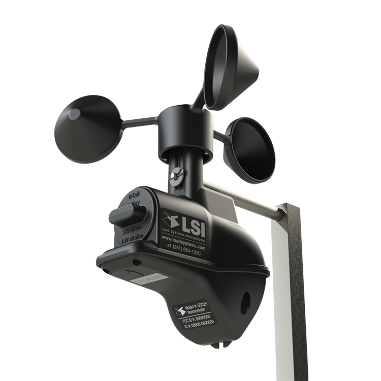
Before proceeding read and understand the following:
For your safety and that of the people that come into contact with LSI products, understand the significance of the instructions included in this guide, respect all laws and regulations and comply with applicable standards. Pay particular attention to items bearing the alert symbol:
![]() 

and the following words:
![]()
Important: this denotes an instruction that if not complied with may lead to product performance issues.
 2.8 Crane Wireless Wind Speed Installation
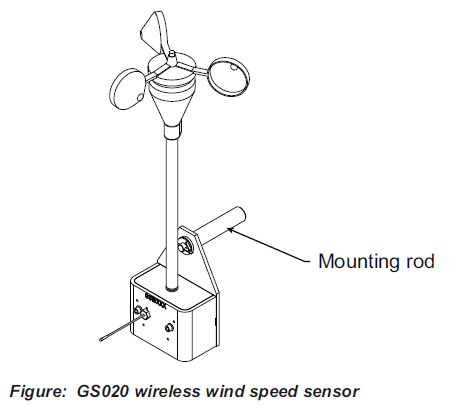
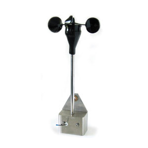
1. Prepare for the crane wireless wind speed installation by remove the mounting rod from the wind speed sensor.

2. Determine the mounting rod position for the crane wireless wind speed installation
a. Install the mounting rod on the same side of the boom as the cabin mounted display, perpendicular to the boom, and at the highest point possible.
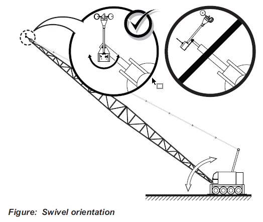
b. The wind speed sensor must pivot freely on the mounting rod at all boom angles.
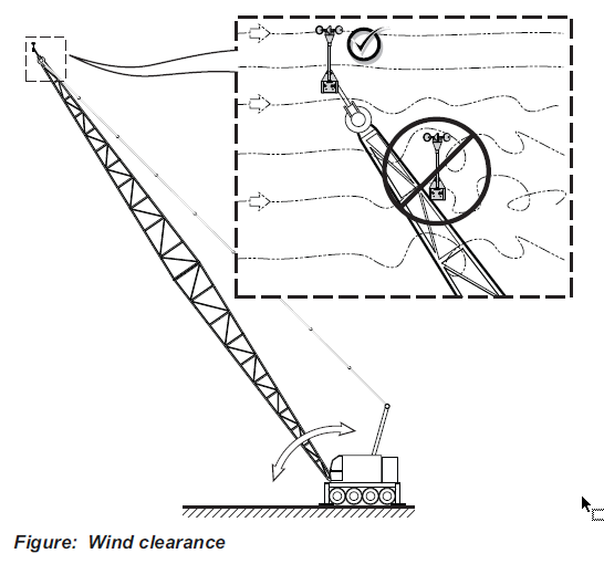
c. The wind cups must be fully exposed to the wind and spin freely at all boom angles.
d. There should be a clear and unobstructed line of sight between the wind speed sensor antenna and the cabin mounted display unit.
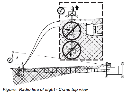
e. Remember for the crane wireless wind speed installation the transmitter antenna should not contact any metal object.

3. Weld or screw the mounting rod to the boom at the selected position.
4. Re-position the wind speed sensor on the mounting rod, add the washer and secure with the cotter pin.
 Free Quote
(OR USE INDEX TO CLICK ON SECTION NEEDED)
1.1 OVERVIEW
1.2 START-UP
2.1 DISPLAY GS550
2.1a Mounting Bracket
2.1b Antenna Position
2.1c Power Supply and Lockout Connection
2.1d Lockout Settings
2.1e Password Settings
2.3 ANGLE SENSORS FOR THE BOOM OR JIB
2.3a Mounting Procedure
2.3b Angle Calibration Procedure No 1: Mechanical Set-Up
2.3c Angle Calibration Procedure No 2: Correct with the GS550
2.4a Switch Bracket Installation LB011
2.4b GS050 Installation
2.4c GS075B Installation
2.4d Chain length adjustment
2.5a Maximum Boom Extension
2.5b Mounting the Cable Reel
2.5c Boom Length Calibration Procedure No 1: Mechanical Set-Up
2.5d Boom Length Calibration Procedure No 2: Correct with the GS550
2.6a Radius Verification and Adjustment
2.6b Radius Settings
2.6c Basic Radius Parameters for a Lattice Crane
2.6d Basic Radius Parameters for a Telescopic Boom Crane
2.6e Advanced Radius Parameters
2.7 CRANE WIRELESS WIND SPEED INSTALLATION
2.8 WIRELESS LOAD PINS
2.8a LP011, LP015, and LP026
2.8b Load Pin Transmitter GS001
2.9 LINE RIDING TENSIOMETER
2.9a Line Riding Tensiometer Installation
2.9b Line riding tensiometer installation on a swing arm
2.10 LOAD PINS, LINE RIDING TENSIOMETERS AND COMPRESSION CELLS: CALIBRATION
2.11 FOUR POINT LIFT
2.11a Sum Load Indication
2.11b Imbalance
2.11c Slack Rope
2.12 LIST AND TRIM ANGLE SENSOR
2.12a Programming the GS550 for List and Trim Indication
2.12b Mounting Instructions
2.12c List and Trim Angle Calibration Procedure
2.13 ROPE PAYOUT
2.13a Rope Payout Calibration Procedure No 1: Mechanical Set-Up
2.13b Rope Payout Calibration Procedure No 2: Correct with the GS550
2.13c Rope Payout Limits
2.13d Electrical connections
2.14 SLEW SENSOR INSTALLATION
2.14a Encoder Gear Verification
2.14b Slew Encoder Location
2.14c Slew Encoder Orientation
2.14d Slew Encoder Installation
2.14e Slew Transmitter Location
2.14f Slew Transmitter Installation
2.14g Cable Length Adjustment
2.15 SLEW SENSOR CALIBRATION
2.16 DATALOGGER
2.16a Recording Modes
2.16b Date and Time
2.17 SENSOR LIST
2.17a How to Add a Sensor to the GS550
2.17b How to Remove a Sensor from the GS550
2.18 NETWORK OPTIONS
2.18a Listen Only Mode
2.18b Repeater
2.18c Wireless Sensor Update
3. OPERATION
3.1 DISPLAY GS550
3.2 USB PORT
3.3 KEYPAD
3.3a Tare
3.3b Info
3.3c Limit
3.4 DISPLAY ABBREVIATIONS
3.5 SYSTEM MENU
3.5a Menu Numbers
3.5b Menu Navigation
3.5c Password Protection
3.5d Menu Layout
3.5e Parts of Line
3.6 RATED CAPACITY INDICATORS
3.6a Display Programming
3.6b Crane Rigging
3.6c Chart Wizard
3.7 DISPLAY SETTINGS
3.7a Weight Units
3.7b Wind Units
3.7c Language
3.7d Light Intensity
3.7e Contrast
3.7f Backlight Mode
3.8 SYSTEM DIAGNOSTIC
3.8a System Sensors Diagnostic
3.8b Radio Network Diagnostic
3.8c Lockout Diagnostic
3.8d Display Diagnostic
3.8e Digital Input Diagnostic
3.9 WORK AREA MANAGEMENT
3.9a Set Fixed Limits
3.9b Set Dynamic Limits
3.9c Clear all work area limits
3.9d Warning, alarm and lockout
3.9e Slew and work area display
4. USB TOOL
4.1 DATA LOGGER TRANSFER FROM DISPLAY
4.1a Transfer from display to USB device
4.1b Transfer from USB device to PC
4.1c Troubleshooting
4.2 UPLOAD CAPACITY CHARTS
4.3 DATA LOGGER VIEWER
4.3a Installation on a PC
4.3b Quick Start
4.3c Full Report
4.3d Wind Report
5. MAINTENANCE
5.1 SENSORS
5.1a Replacing Sensor Battery
5.2 ANTI-TWO-BLOCK SWITCH
5.2a Replacing the GS050 Batteries
5.2b Replacing the GS075B Battery
5.3 REPLACING A SENSOR ANTENNA
5.4 LOAD CELLS
5.4a Reading Accuracy
5.4b Load Testing
5.4c Care
6. TROUBLESHOOTING
7. CERTIFICATION NOTES
7.1 MODEL NUMBERS
7.2 IMPORTANT NOTES FOR HAZARDOUS AREA CERTIFIED COMPONENTS
7.2a Specifications
7.2b Ensuring Safe Operation in Hazardous Areas
7.2c Product Repair And Servicing
7.3 EQUIPMENT MARKINGS
7.4 GS550 DISPLAY LABELS
7.5 CLASS 1 DIVISION 1 AND DIVISION 2 CERTIFICATIONS
7.6 ATEX CERTIFICATIONS
7.7 FCC AND IC – INSTRUCTIONS TO THE USER
7.8 EMI / EMC
7.9 ENVIRONMENTAL CONDITIONS
7.10 CE
7.10a Declaration of conformity
7.10b CE Safety
8. GS550 MENU OUTLINE
9. LSI PRODUCT LIMITED WARRANTY – 2009/02/16
9.1 LIMITED WARRANTY
9.2 WARRANTYSERVICES PROCEDURES
9.3 EXCLUSION OF OTHER WARRANTIES
9.4 EXCLUSION
9.5 LIMITATION OF LIABILITY
9.6 RECOMMENDED PRACTICES
9.7 CHOICE OF LAW
9.7a Entire Agreement


