BTS is a leading provider of PAT Hirschmann LMI components including the PAT DS85 replacement consoles. With 38 years of industry experience, and thousands of customers across the world, you can trust that we provide fast cost effective service. Contact us toll free in the US at 855.BODE.TEC or internationally at +1.303.433.8878
PAT DS85 Replacement Procedure
Replacement of an aging PAT DS85 system is a simple process of removing your old console and plugging in a new one. There are two main components of the LMI system that are involved in this replacement process. The fists is the replacement of the actual display console itself. The second is the download and re-upload of your existing crane specific software. Its a simple three step process:
- Unplug the existing console and ship it to one of our locations.
- Our technicians will extract the crane specific software from the old console, upload it to the new DS85, and send the new one back.
- When the new console arrives simply plug it back in and the process is complete
General PAT DS85 Description
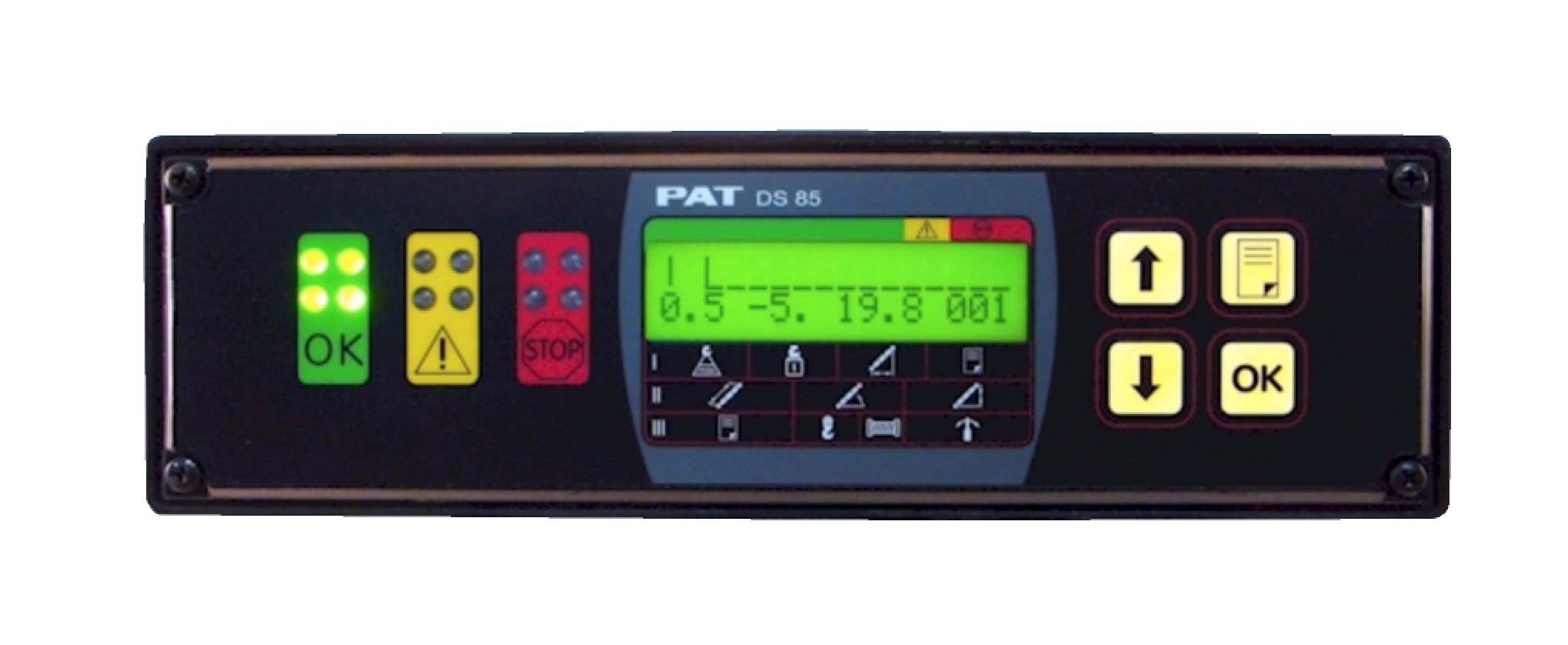
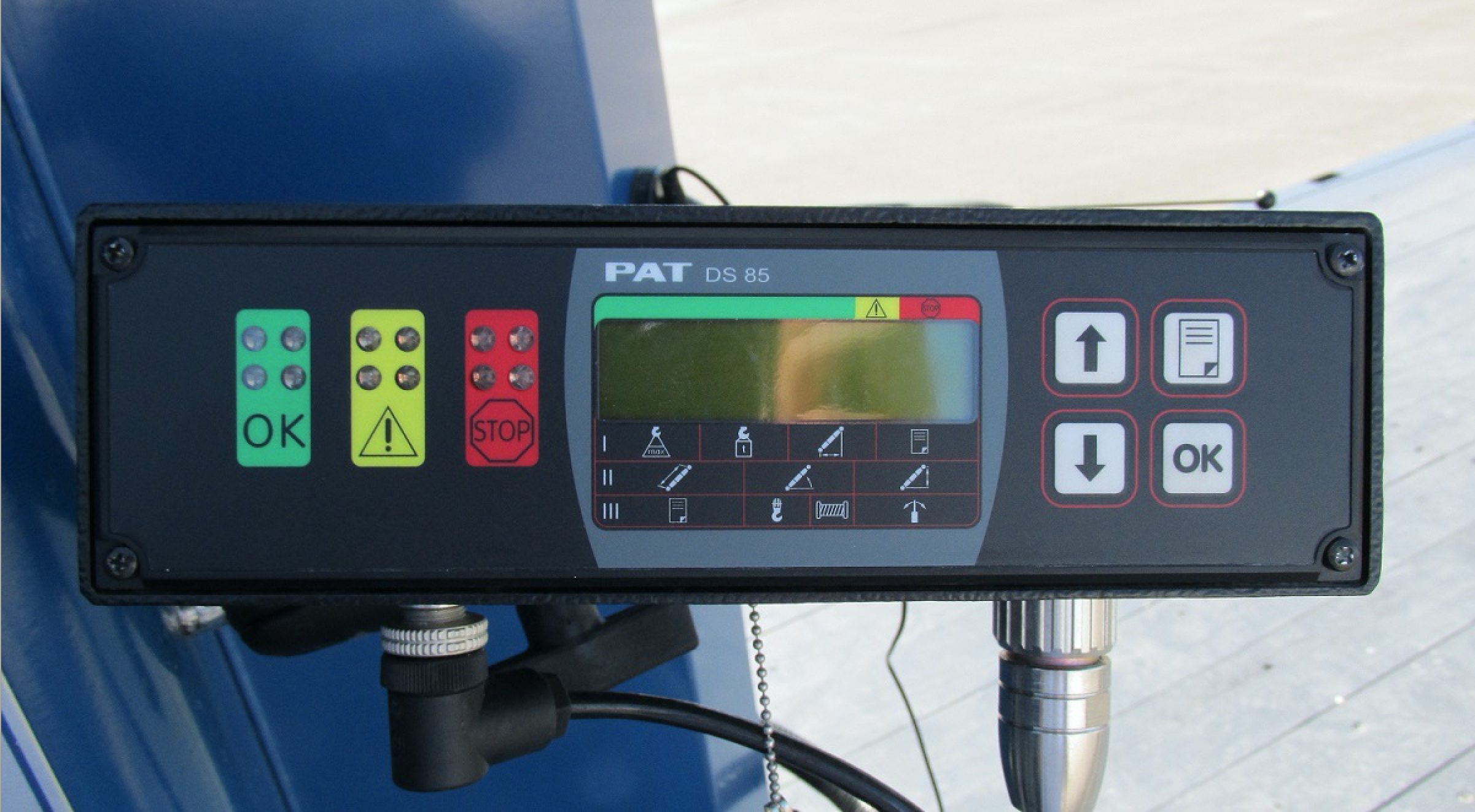
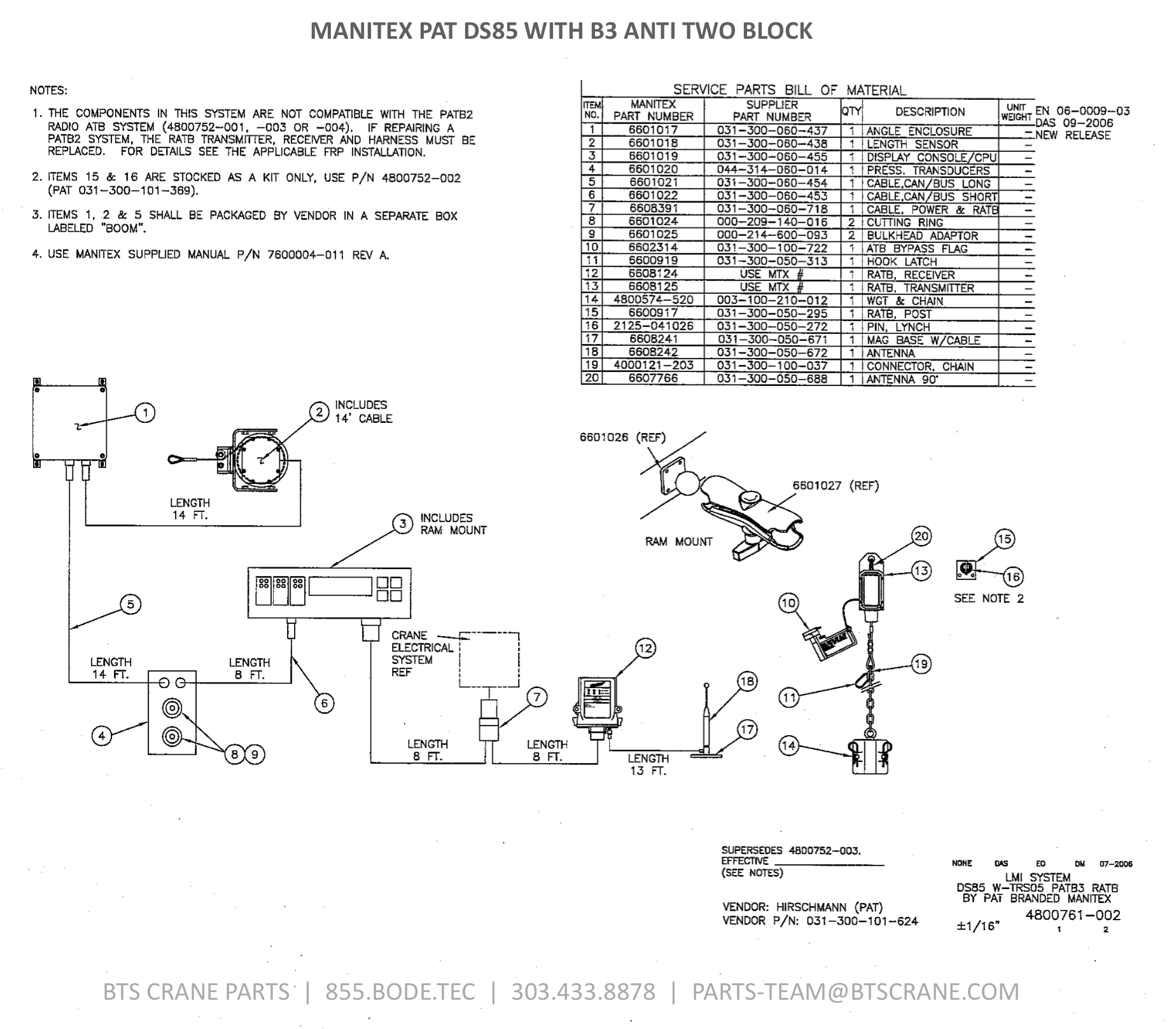
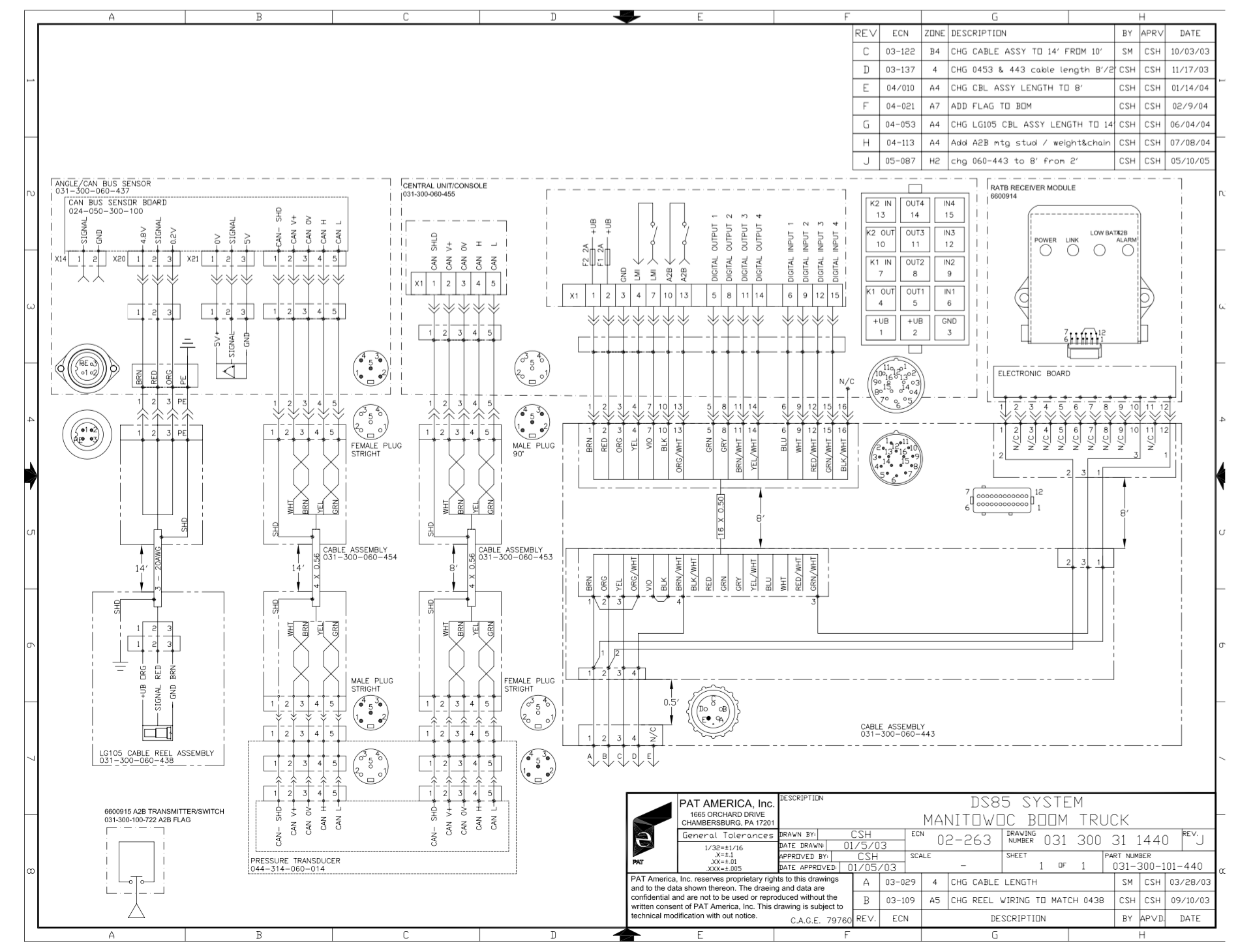
The PAT DS 85 system is a CAN bus system consisting of a central micro processor unit or operating console, length and angle sensor, pressure transducers, and anti-two block switch.
The Load Moment Indicator system operates on the principle of reference/real comparison. The real value, resulting from the pressure measurement is compared with the reference data, stored in the central processor memory and evaluated in the micro processor. When limits are reached, an overload warning signal is generated at the operator’s console. At the same time, the movement causing the error such as hoist up, telescope out and boom down, will be stopped.
The fixed data regarding the crane, such as capacity charts, boom weights, centers of gravity and dimensions are stored in memory in the central processor unit. This data is the reference information used to calculate the operating conditions.
The operating modes are selected by the operating mode key on the console by scrolling through the text messages defining the boom truck configuration.
The crane load is measured by pressure transducers attached to the piston and rod side of the hoist cylinders.
Boom length and boom angle are transmitted by length/angle CAN bus node mounted on the side of the boom in the angle sensor box. The length sensor/cable reel is mounted inside the base which measures the boom length.
The PAT RATB works like our normal Anti-Two-Block. It alerts to an impending two-block condition. This alert can come in the form of an audible alarm and visual LED or with the optional function lockout if the crane is so equipped. The radio anti two block transmitter switch transmits a error condition when the switch closes or transmits an OK signal, no less than every two seconds to the receive. The transmitters send a unique serialized frequency on up to three separate channels to ensure accurate and consistent reception of data and to reduce the possibility of unnoticed failure. The transmitter is powered by 4 C batteries. The receiver is mounted into a receiver box locate near the operating station. The receiver box provides the following indications: Power (status), LINK, Low Battery, and A2B. The receiver will work 10...32VDC and fused to 1 Amp.