PAT DS150 Boom Truck Operators Manual for Manitex and Other Cranes
1 General Information
The PAT DS150 Boom Truck Load Moment Indicator (LMI) complements the operator’s skill by providing the information needed to make the demanding lifts required of modem cranes and displaying it in the operator’s cab.Using various sensing devices, the LMI monitors all crane functions and provides the operator with a continuous reading of the crane’s rated capacity. The readings continuously change as the crane moves through the motions needed to make the lift. If hazardous conditions are approached, the LMI is designed to warn the operator by sounding an audible alarm and illuminating a warning light.
The LMI also provides the operator with information concerning certain geometrical data such as main boom length corresponding to the selected operating code, main boom angle, jib angle, jib length,operating mode and weight of the load on the hook, and the total weight being lifted by the crane.
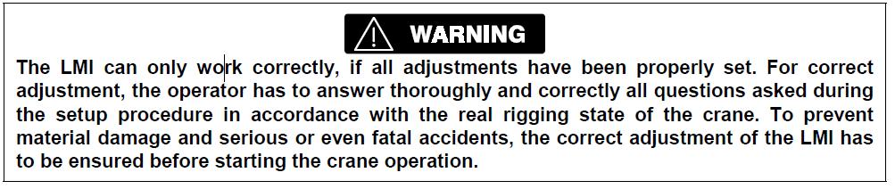
2 Warnings
- The LMI is an operational aid that warns a crane operator of approaching overload conditions and over hoist conditions that could cause damage to equipment and personnel.
- The device is not, and shall not, be a substitute for good operator judgment, experience and use of accepted safe crane operating procedures.
- The responsibility for the safe crane operation shall remain with the crane operator who shall ensure that all warnings and instructions supplied are fully understood and observed.
- Prior to operating the crane, the operator must carefully and thoroughly read and understand the information in this manual to ensure that he knows the operation and limitations of indicator and crane.
- Proper functioning depends upon proper daily inspection and observance of the operating instructions set forth in this manual. Refer to Section 6. Pre-Operation Inspection and Calibration Verification of this handbook.
3 PAT DS150 Boom Truck LMI System Description
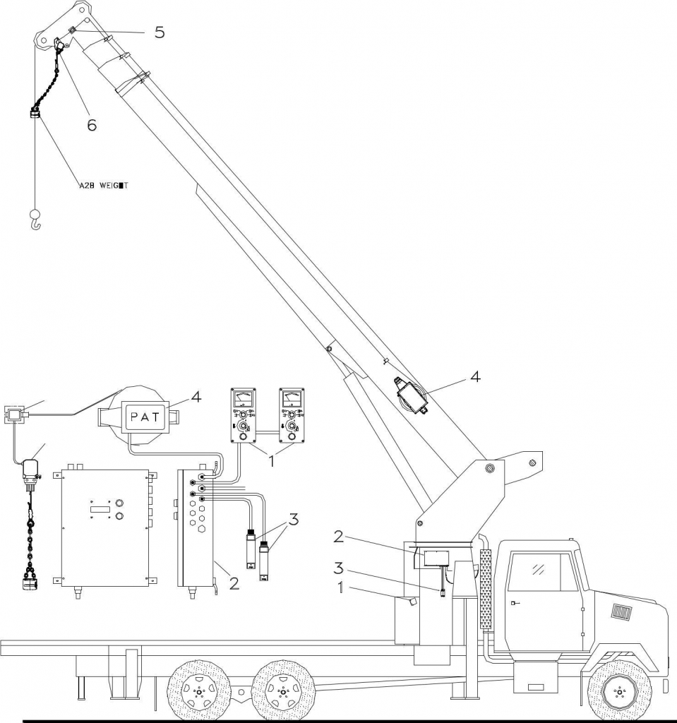
Fig. 1: Components of the LMI System PAT DS150 Boom Truck
- Operator’s Console
- Central Unit
- Pressure Transducer
- Cable Reel
- Boom Tip Junction Box
- A2B Switch
The PAT DS150 Boom Truck Load Moment Indicator (LMI) System consists of a central microprocessor unit,operator consoles, length/angle sensor, pressure transducers and an anti-two-block switch.
The system operates on the principle of reference/real comparison. The real value, resulting from the pressure measurement and geometric sensors, is compared with the reference data stored in the central processor memory and is evaluated in he microprocessor. An analog indication of % capacity is displayed via an operator’s console. When limits are reached, an overload warning signal is generated. At the same time, the crane movements that increase load moment such as hoist down, telescope out, and boom down will be locked out.
The fixed data regarding the crane, such as dimensional data, capacity charts, boom weights, and centers of gravity are stored in memory chips in the central processor unit. This data is the reference information used to calculate the operating conditions.
Boom length and boom angle are registered by the length/angle sensor, located inside the cable reel, mounted on the boom. The boom length is measured by the cable reel cable, which also serves as an electrical conductor for the anti-two- block switch.
The crane load is measured by pressure transducers attached to the piston and rod side of the lift cylinder.
Controls on the operator’s console allow the operator to select the operating mode (main boom, jib,etc.) as well as the parts of the line currently in use. The system will then limit operation to the capacities on the selected load chart, or the maximum permissible line pull in that configuration.
After the engine is started and the PTO is engaged, the LMI powers up and conducts an automatic test of the complete system.
After two successful system tests without errors, the system is ready for operation. In case of a system error, both the overload and anti-two-block lights on the central unit will illuminate.The interactive user guidance considerably simplifies the input of operating modes as well as the setting of geometry limit values.
4 System Components
4.1 Console Operation
The PAT DS150 Boom Truck Load Moment Indicator (LMI) system utilizes a system console at each operator’s station. The purpose of this console is to display relative load moment data to the operator and allow the operator to input specific data concerning the configuration of the crane. The console (Figure 3) has four basic components:
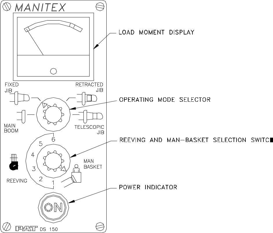
Figure 2. DS150 Operator’s Console
4.1.1 Load Moment Display
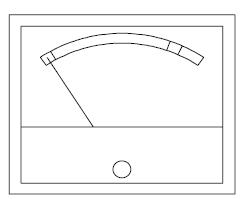
This is an analog indication of relative load moment. It is displayed in terms of % capacity at the given configuration and position of the boom. The meter is broken into three areas: the green bank is 0 to 90% capacity; the yellow band if 90 to 100% Capacity; and the red band is overload
4.1.2 Operating Mode Selector
This switch allows the operator to select the current crane configuration. The four positions translateas follows:
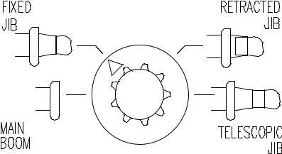
Pos. 1 – Main Boom Only
Pos. 2 – Fixed Jib
Pos. 3 – Telescopic Jib Retracted
Pos. 4 – Telescopic Jib Extended
By selecting the appropriate configuration, the LMI system can utilize the proper load chart for establishing machine capacity
4.1.3 Reeving And Man-Basket Selection Switch
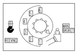
This selector switch allows the operator to input the reeving (parts of line)or man-basket configuration being utilized. The importance of this data is to allow the system to monitor line pull capacity relative to the crane load for each of the reeving configurations available. The man-basket position changes the operating mode of the crane to a load chart that is in conformance with the requirements of ANSI A92.9-1979 for aerial devices.
Reeving selections: When the crane load exceeds the maximum line pull capacity based on the parts of line selected, the system will alert the operator by activating the audible alarm, and crane functions will shut down on units equipped with the overload “shut-off” option.
Man-Basket selection: When the man-basket load exceeds the maximum capacity of the operating mode the system will alert the operator by activating the audible alarm and crane functions will shut down on units equipped with the overload “shut-off” option.
4.1.4 PAT DS150 Boom Truck Console Power Indicator
 This “button” indicator allows the operator to select which console is functional. When starting crane operation, the operator determines whether the console at his station is functional by the illumination of this button”. If the “button” is not illuminated, the operator then depresses the “button” which will switch control to the console at his location. When the console is powered, the analog meter will display % capacity, and all switch positions selected will be functional.
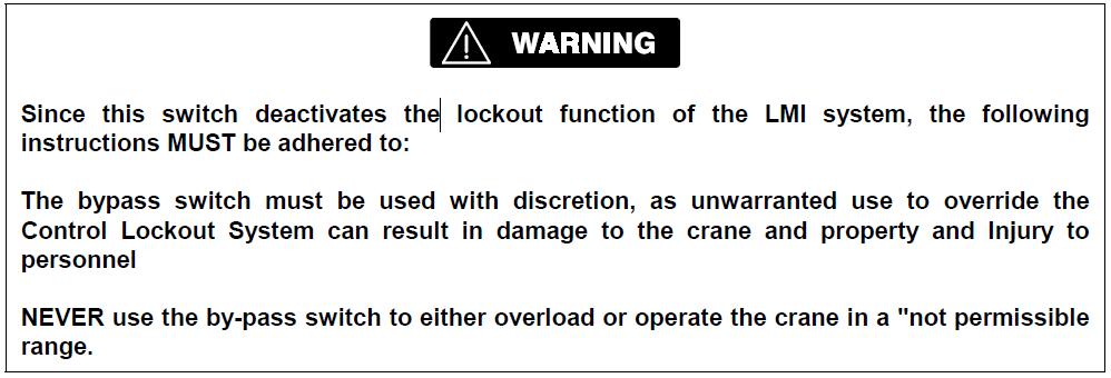
4.2 Control Lockout Override Key Switch (Optional)
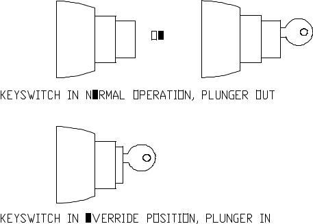
A key-actuated switch, installed on the service console, enables the operator to “override the control lockout feature for the load/moment circuits.The switch is spring-loaded
to return from the “in or override” position to the “out or normal” position after it is released. In the override (in) position, the key cannot be removed.
NOTE: This option does not affect the A2B control lockout circuit.
5 Pre-Operation Inspection And Calibration Verification
Before operating the crane, perform the following Pre-Operation Inspection and Calibration
Verification
-
- Check the electrical wiring connecting the various parts of the system for physical damage.
- Check the anti two-block switches and weights for free movement.
![]()
-
- If the operator cannot see the load-handling device approaching the boom nose, he shall have an assistant (signal person) watch the load-handling device. The operator shall be prepared to stop the machine immediately should the LMI system not function properly as indicated by lighting the red warning light (4), sounding the audible alarm (12) and locking the crane movements, hoist up,telescope out and boom down.
- Check the anti two-block alarm light (4) and the audible alarm (12) by performing one of the following tests:
A. By manually lifting the weight attached to the anti two-block switches. When the weight is lifted,the audible alarm (12) should sound, the anti two-block alarm light (4) should light.
B. Slowly raise the main boom load-handling device to create a potential two-block condition.When the load-handling device lifts the weight, the audible alarm (12) should sound, the anti two- block alarm light (4) should light and the motion of the load-handling device should be stopped. Lower the load-handling device slightly to eliminate this condition.
C. Slowly lower the boom to create a potential two-block condition. When the load-handling device lifts the weight, the audible alarm (17) should sound, the anti two-block alarm light (24) should light and the boom lowering function should be stopped. Lower the load-handling device slightly to eliminate this condition.
![]()
- If the crane is equipped with a boom extension, repeat the test procedure for the boom extension anti two-block switch.
- Check that the display of the main boom angle agrees with the actual boom angles.
- Check that the display of the operating radius of the crane agrees with the actual radius.
- Check the load display by lifting a load of known weight.
6 Service And Maintenance
Maintenance of the PAT DS150 Boom Truck Load Moment Indicator System consists of inspecting:
- The cabling connecting the various parts of the system. If a cable is
damaged, it must be replaced immediately. - The insulation of the length sensor cable and the cable guides. If the insulation is worn or the cable damaged, these parts must be replaced.
- Check the anti-two-block limit switches for freedom of movement
- The cable reel must be properly tensioned to operate properly
- Check the pressure transducers at the lift cylinder and the connecting hoses for oil leakage.
Other than correcting the problems identified in the Malfunctions Table (refer to next section) and replacing faulty mechanical parts and cables, no other repairs are to be performed by operating personnel. All other repairs must be performed by PAT Authorized Service Representatives.
7 Troubleshooting
The PAT DS150 boom truck service console displays 16 variables to assist the setup and diagnostics of this system. The first numeral displayed is the reference number I thru 16. The second value displayed is as follows:
REF # VALUE
- Main Boom Length
- Main Boom Angle
- Radius
- Jib Angle (with jib only, otherwise blank)
- Tip Height
- Operating Mode
- Error Code (in case of error only, otherwise blank)
- Real Moment
- Jib Length (with jibs only, otherwise blank)
- Rated Load (in t or 1,000 lbs)
- Actual Load (in t or 1,000 lbs)
- Reeving
- Load Moment in %
- Piston side Pressure in mV
- Rod side Pressure in mV
- Test
By depressing either the page up or page down” button, the display will sequence through the
variables.
In case of a malfunction of the system, both the OVL and A2B lights will illuminate simultaneously. By selecting variable #7 on the service console, the display will indicate a code, which identifies the system malfunction.
The error codes listed in the Malfunction Table will identify various faults, which can occur with the LMI. Following the Malfunction Table is information, which explains each fault and describes the action, which should be taken to correct the fault.
Error codes 7 through 99 are faults within the electronic microprocessor and must be repaired by factory-trained service personnel. When these faults occur, an authorized PAT service organization must be contacted.
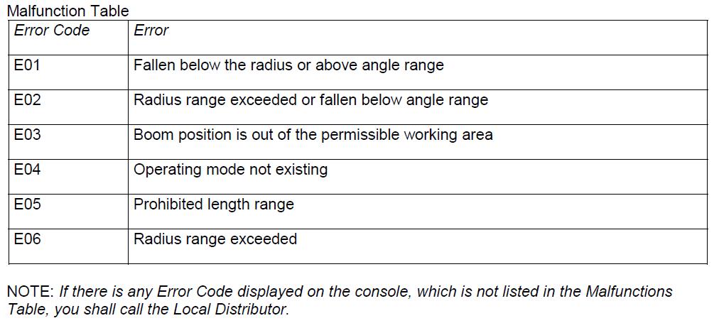
PAT DS150 Boom Truck Operating Errors
Malfunctions in the system, which are caused by, range exceeding or operating errors by the crane operator himself are indicated on the display together with an explanation. Error codes E01, E02, E03, E04, (E05), can normally be eliminated by the crane operator himself.