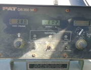
Recently one of our customers was having some issues with an unstable PAT DS350 crane angle display on a Liebherr LTM1160. Our crane repair technicians provided him with some simple tests to narrow down what his problem may be:
PAT DS350KD Crane Angle Display Test:
1. Testing external wiring and angle sensor. Temporary wire replacement between DS350KD Central Unit (behind the seat) and angle sensor in PAT cable reel.
a. Switch off crane power and remove the PAT Hirschmann central unit cover.
b. Make a note of each wire number or wire color that is connected in the green terminals X1/32, X1/33 and X1/35. You need to return those wires back to the correct terminal when done.
c. Refer to the sketch below.
i. X1/32 = GND (Electronic Ground – not Crane Ground) for crane cable reel with crane angle sensor
ii. X1/33 = Angle signal from angle sensor
iii. X1/35 = – 5V (that is minus 5V) power supply to cable reel with angle sensor
d. Remove the existing wires at the main board terminals X1/32, X1/33 and X1/35.
e. Open the PAT cable reel on the crane boom.
f. Make a note of the cable numbers or color code of each wire connected to the cable reel terminal 1, 3 and 4. You need to return those wires after testing to the correct terminals.
g. There should be a jumper from 1 to 5 and 2 to 6. Leave those jumpers in the terminals as they are. Ensure good condition and termination of those jumpers. A poor connected jumper can cause the angle problem as you described.
h. Remove the wires (coming from the central unit) from cable reel terminal 1,2 and 4. Ensure that the appropriated wires are disconnected at both ends, the central unit and the crane cable reel.
i. Make yourself three long jumpers with single wire, minimum wire gauge AWG16, that are long enough to reach from Central unit to the cable reel. Preferably different colors to avoid mix up.
j. Connect the main board (Central unit) terminals:
i. X1/32 with cable reel terminal 1
ii. X1/35 with cable reel terminal 3
iii. X1/33 with cable reel terminal 4
k. Switch crane power on and test stability of angle indication.
i. If stable, the problem is in the wiring.
ii. If unstable the problem is somewhere on the main board, the crane angle sensor, or radio interference near the crane.
l. After testing, switch crane power off and return wiring as you noted to their original conditions.
2. Testing Central Unit components, such as main board, AS110 components, etc. by simulating a fixed angle signal of 45 degree.
a. Perform same steps as described in item 1a to 1d.
b. Obtain 2 Resistors 4.7kOhm (Radio Shack or other electronic store) ¼ Watt / 5 or 10% tolerance.
c. Install the resistors into the main board terminals X1 (central unit) as described below
i. First resistor between X1/32 (first leg) and X1/33 (second leg). Ensure that both sides (legs) of the resistor do not short out. Note there is no polarity on resistors – it doesn’t matter which way they are placed.
ii. Second resistor between X1/33 (first leg) and X1/35 (second leg). Ensure that both sides (legs) do not short out. Note that there is no polarity on resistors. Note that terminal X1/33 has two legs in the terminal the second leg of the first resistor and the first leg of the second resistor.
iii. Ensure the legs are not shorting to GND or any other circuit.
d. Switch crane power on and the console should indicate approximate 45 degree boom angle. Of course when you boom up or down this value will not change as it is a fixed signal produced by the resistor network that you created by installing this. It acts like a voltage divider.
e. If angle indication stays stable – main board and central unit components are good. If not stable – problem locate on central unit parts, such as main board, AS110 component, central unit internal wiring or A/D converter, etc. In this case professional services are definitely needed to continue. Please contact Bode Technical Services.
f. Note, that for both test (1 and 2) a long enough test period is required to obtain and observe the condition under different heat conditions. Also, swing is recommended to observe any pattern of boom direction. This is important to rule out any radio interference.


