PAT DS 150
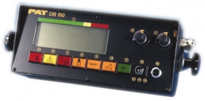


The PAT DS-150 was designed as a more cost effective LMI system for use in small telescopic boom mobile cranes. The DS 150 is installed and calibrated to the crane’s load chart. The system allows operators to work with confidence by giving them constant access to the information they need.
DESCRIPTION OF THE PAT DS 150 CENTRAL UNIT
All the data of the crane is stored inside the central unit in EPROM’s. The central unit receives all actual information of the crane. This is computed against the reference data and the crane status is continuously monitored.
Description of the Housing
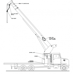
The PAT DS 150 central unit is a rugged, waterproof sheet steel housing. It is mounted on the left side of the turn table weldment or on the counterweight. The cables are led into the central unit via strain reliefs and connected with fast-ons. An override switch is mounted on the housing, which overrides the LMI function. The system is protected by a 2-AMP fuse, which is mounted on the lower right side. The output signal is protected by a 10-AMP fuse, mounted on the lower mid.
Description of the Boards
Inside the central unit (CU) there is a main board. The main board and CPU is the heart of the system, and it contains the processor and the system and data EPROMs. The system EPROM holds the operating system and data EPROM hold the crane and calibration information. The wires from the various components are connected with fast-ons to the main board. The main board holds the electronics necessary to receive, evaluate, and direct the continuous flow of data from the sensors to the processor.
Main board components
- Power supply – Provides all the necessary voltages for the transducers and the electronics on the main board.
- Analog input part -Receives and prepares all the signals from the transducers for further processing. Relays, an overload and anti-two-block relay: Controls the Bosch relay for lever lockout.
- Incoming Signals-Signals from the transducers are connected to the main board. The signals vary depending on the sensor:
- Angle transducer signal is between -1.875V and -3.125V
- Length transducer signal is between -0.500V and -4.500V.
- Pressure transducer signals are between 0.00V and -1.00V. (measured between the negative and positive outputs)
- Anti-two-block switch resistance is 4.7Kohms.
- Digital inputs for the duty selection switches are on or off.
- Outgoing Signal- The outgoing signal of the main board is the signal for lever lockout of connection #48. In normal working conditions there are 12 volts at this connection. If there is an overload or anti- two-block condition the signal becomes 0 volts. Furthermore, all voltages for the transducers are going out through the main board.