
HIRSCHMANN MAESTRO INSTALLATION GUIDE


1 General Information
This guide describes the procedure for installation of the Hirschmann Maestro and DS160 Systems as a replacement for older PAT LMI systems especially the PAT DS350 and PAT DS50. Well-grounded knowledge regarding the functionality of load moment indicators as well as knowledge of the start-up procedure and adjustment of such systems is required. If you have questions at any point, and have purchased this upgrade kit from BTS Crane, please feel free to contact us for free installation support; toll free in the US at 855.BODE.TEC, or worldwide at +1.303.433.8878
Please always comply with manufacturer safety instructions.
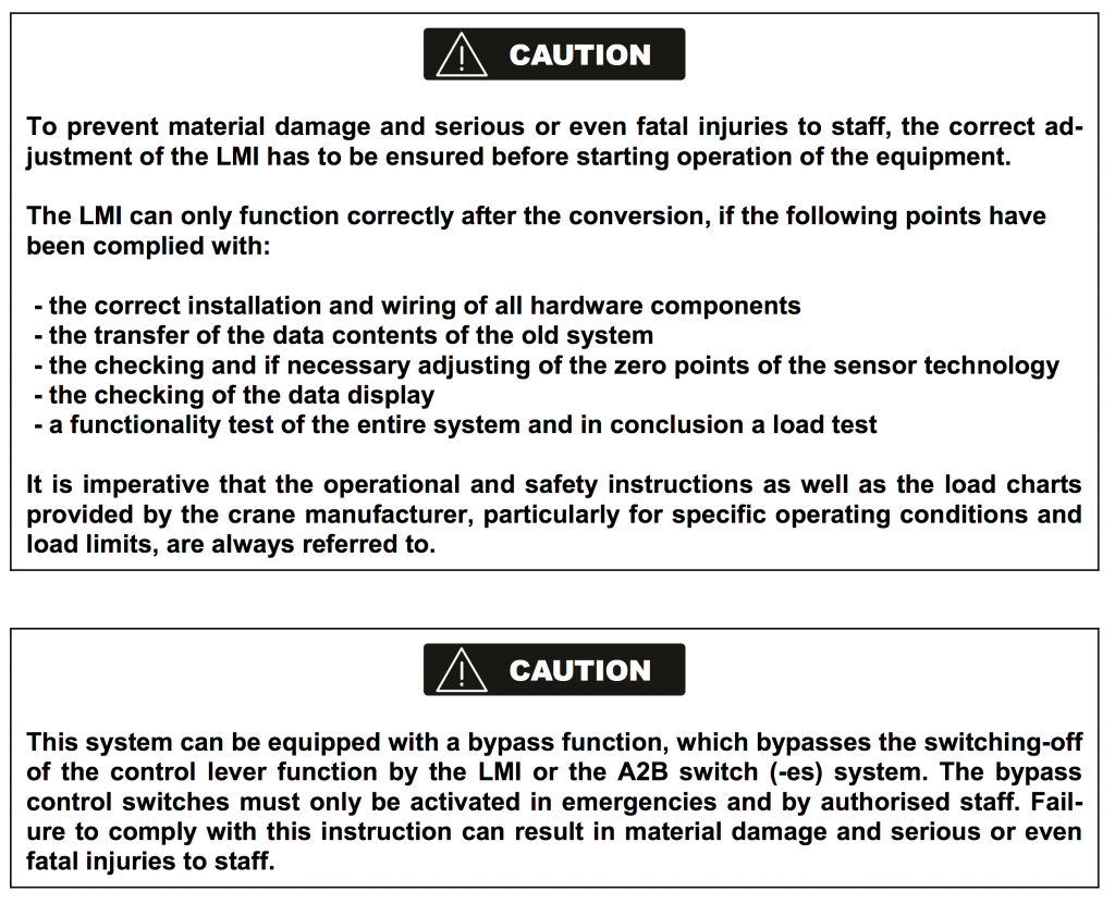
2 Hirschmann Maestro Safety Instructions
The following safety instructions must always be observed and complied with.
2.1 Tools required
- Installation tools for mechanical and micro-electric work as:
- Multimeter
- Tools for Wiring–crimping tool, knife, cutter etc.
- Screw Drivers
- Wrenches
- Soldering Iron
- Digital Level
2.2 What is new or changed?
- The central unit has been upgraded to the new more compact maestro central unit.
- The maestro console in now used in place of the DS 100, DS 200, DS 350 KD/LC, DS 350 G,E,GW consoles.
- Pressure Transducers, KMD loadcells, SKM lineriders will need to be modified or replaced by current output type sensors (4-20 mA), the kit comes standard with new tranducers.
- You can either use the same cannon plug cables with available adaptors or use new 5 pin cable for pressure / load sensors.
- Data eproms will need to be updated and should be provided with your upgrade kit.
- The lightbar option has been eliminated.
2.3 What remains same?
- The primary cable reel will remain with voltage outputs.
- Anti two block switch remain the same.
- Most cables will remain the same, except for: load sensors, 7 conductor cables from cable reel to C/U, and console cable (all included in kit)
- All digital inputs & output cables remain the same.
- Data eprom from DS 350 G,E & GW and some DS 150 & DS 350 KD/LC’s will remain the same. If the Data Eprom is 27C256, you can use it as-is, otherwise BTS will provide a new eprom for your specific system.
3 Hirschmann Maestro Installation Instructions
The following instructions are to simplify the conversion of the old LMI system to the new HIRSCHMANN Maestro LMI. As always, if you have purchased your kit from BTS, feel free to contact us with any questions that come up during the install.
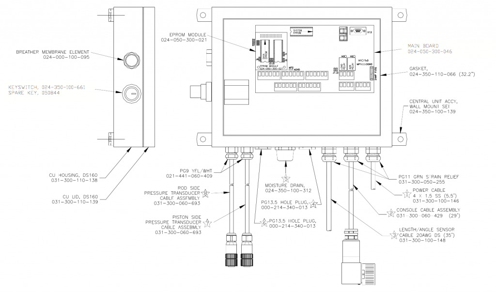
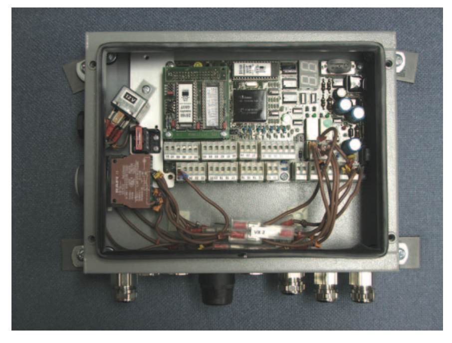
3.1 Central Processing Unit
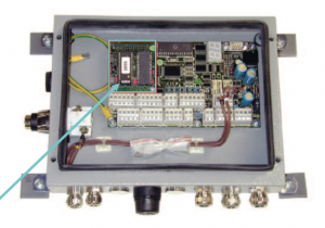
Install the maestro central processing unit in such a way that the old electrical wiring can be retained as far as possible. This can be done to install the Maestro C/U at same place as of Old C/U. However, since Maestro C/U is smaller in size than most of the previous PAT C/U’s, it would be advisable to install it inside the crane cabin behind the operator’s seat. If installing the C/U inside the crane cabin, ensure that the existing cables are long enough to reach inside the cabin after re-routing. Instead of welding the mounting squares of the C/U, you may also use flat bars with holes at each end, enabling the use of the existing holes.
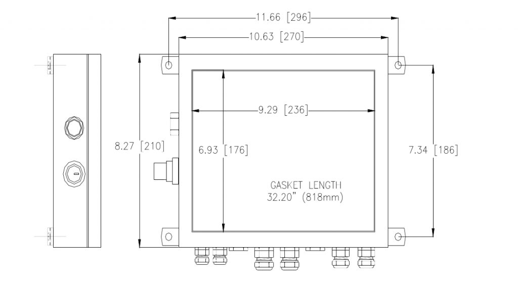
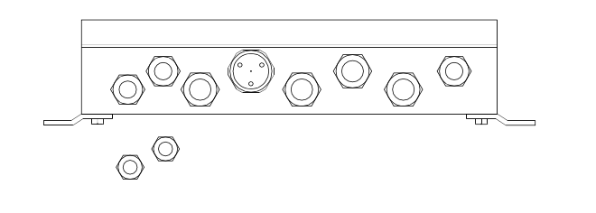
Note that you may be required to modify the strain reliefs in the C/U depending on the amount and size of wires being used. If an extra hole is needed you can remove the breather from the side of the C/U and utilize this hole, always leave a drip loop in the cables for external mounted C/U’s.
3.2 Console
Install the maestro console with proper positioning within the field of vision and operating area of the crane operator. There is a standard length of cable (with multi-pin connector) supplied with the Maestro console. Ensure there is an adequate length of cable between the console and the central unit.
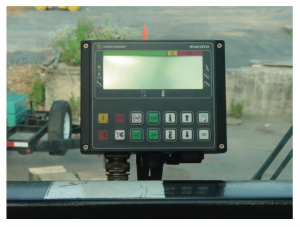
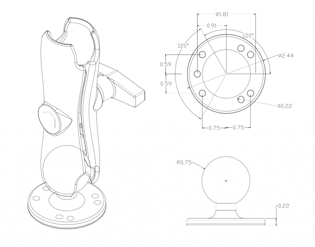
The console has a mount that allows the console to be swiveled into any direction and to be mounted in a variety of locations and on nearly any surface. Choose a location that is in line-of-sight of the sensor and within reach of the operator. Securely attach the two RAM mount bases onto a solid surface for the left and right side operation. The console cable may not fit through goose neck/conduit of previous wiring; therefore, run the console cable to the outside of the conduit and insure there is no interference.
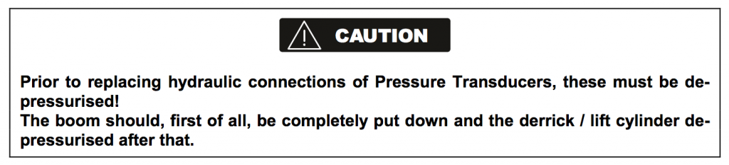
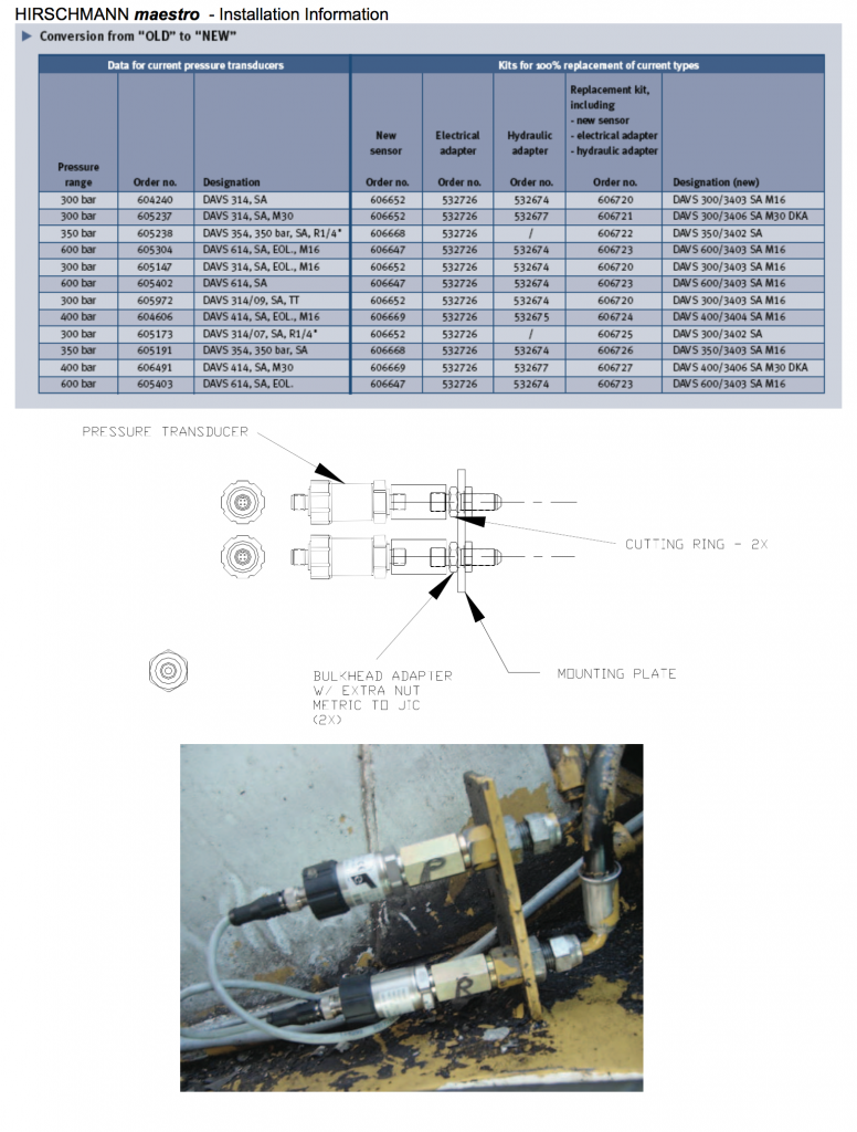
3.3 Pressure Transducers
The pressure transducers of the old system can only continue to be used (in case of GC systems), if these have a signal output of 4…20 mA. A three-pole cable adapter from three-pole canon to M12x1 is available for the electrical connection.
In most older PAT systems, pressure transducers with voltage output are used. These should be replaced with the new DAVS 300/3401 SA type pressure transducers with the same pressure range. It is advisable to also replace the feeder cables at the same time with new cables having pre-assembled connection plugs. These should be included with your BTS Crane Maestro conversion kit.
Pressure Transducer (DAVS300 / 3401) Part Number 031-300-060-452 (4.20mA, 300 bar, M12, 9/16-18)
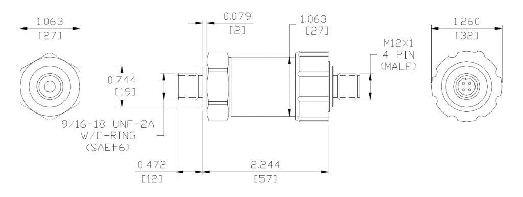
There are no spare parts associated with the pressure transducer; the following parts are use to make a hydraulic connection to a 9/16-18 JIC fitting.
- 000-209-140-016 Pressure Transducer Cutting Ring Seal
- 031-300-050-689 Pressure Transducer Adapter, 9/16-18 UNF-2B, M16 X 1.5
You will need hydraulic adapters to fit the new pressure transducers. The details are shown in this chart:
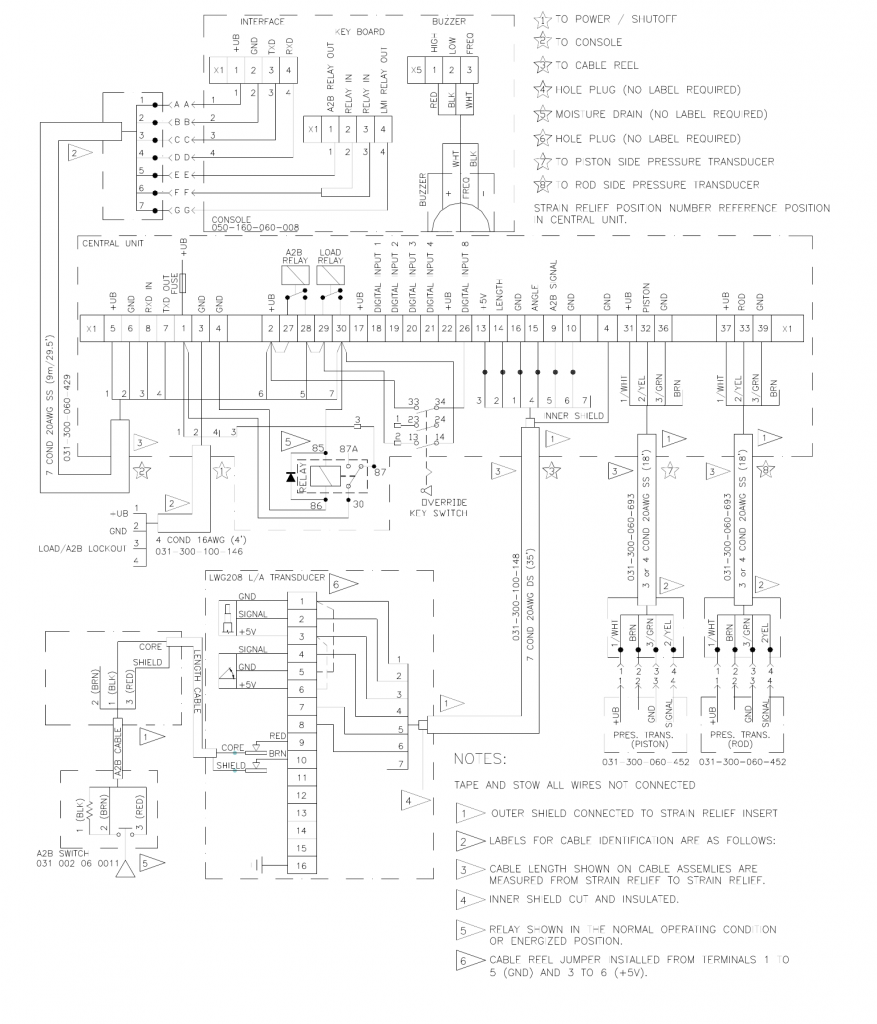
3.4 Maestro System Wiring – 0006 Central Unit
(prior to May, 2006)
3.5 Maestro System Wiring (0011 Central Unit)
(May, 2006 – current)
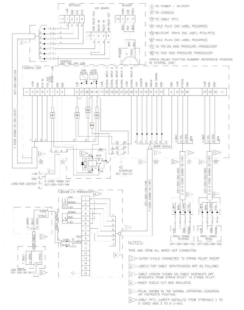
3.5.1 Sensor Installation
Reconnect all sensors and components: length-angle sensor, anti two block signal from cable reel, console, pressure transducers and digital inputs and outputs of the crane electrics (power source and crane lock-outs). Ref. 3.4 maestro wiring diagram.
3.5.2 Relay Installation (maestro central unit 0006)
(Ref. 3.4 maestro system wiring)
1. Connect the wires to the relay as described and shown below:
- Yellow wire to relay terminal #85
- Black wire to relay terminal #86
- White wire to relay terminal #30
- Orange wire to relay terminal #87

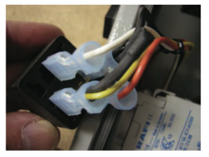
2. Mount the relay to the plastic adhesive holder as shown
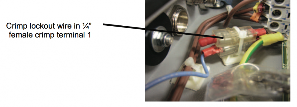
3. The load/A2B lock wire (wire #3 in power cable) should be crimped into the empty 1⁄4” female crimp terminal that is in terminal 1.
3.6 Data Acceptance / Using Data EPROM from Previous LMI System
A distinctive feature of the Hirschmann maestro system is the ability to accept data from multiple older PAT systems (see list in chapter 2.1). Data conversion instructions are provided below. You can insert old data eproms from older systems without any changes in the software. However, the acceptance of these data eproms is limited to the types / system codes given in Chapter 2.1.
If any uncertainty or doubt exists as to whether the data can be accepted in your particular case, please contact BTS Crane to have the conversion capability checked.
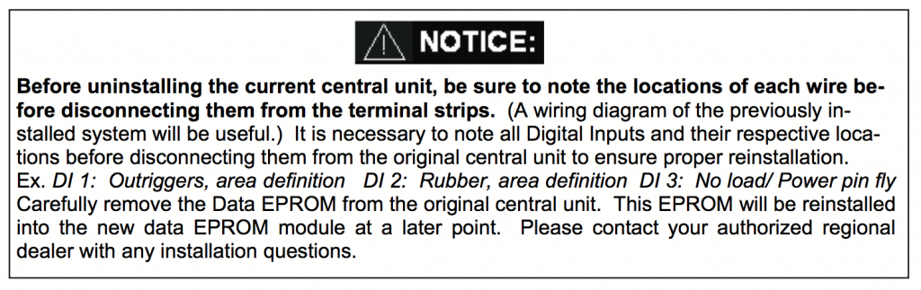
3.7 Data EPROM Extraction from Previous LMI System
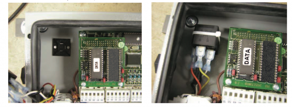
1. Remove cover, from central unit. CAUTION: Before handling the EPROM, discharge any static electricity from your body by touching a grounded point. The EPROM could be damaged by static electricity.
2. Remove the old DATA EPROM, from the main board. Be careful to pull the EPROM out without bending the legs. NOTE: The notch on the EPROM and in the socket determines the correct orientation of the EPROM. Refer to the drawing below for correct EPROM locations.
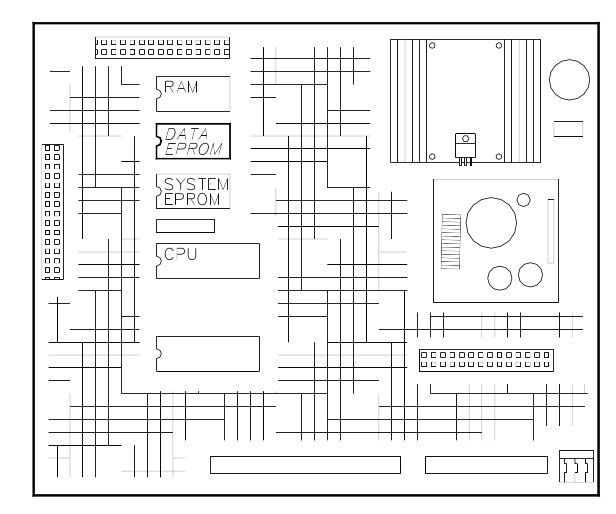
3. Carefully align the new EPROM legs with the socket and push the EPROM into the EPROM module. Be careful not to bend any of the legs.
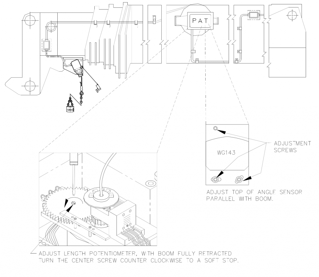
3.8 Cable Reel LWG208/0001 Manual Adjustment Procedure
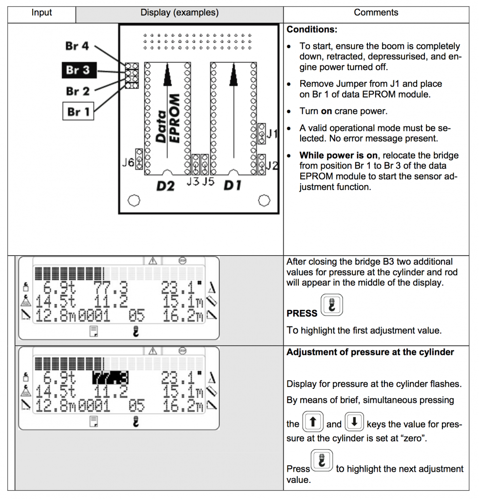
3.9 Automatic Sensor Adjustment via the Console
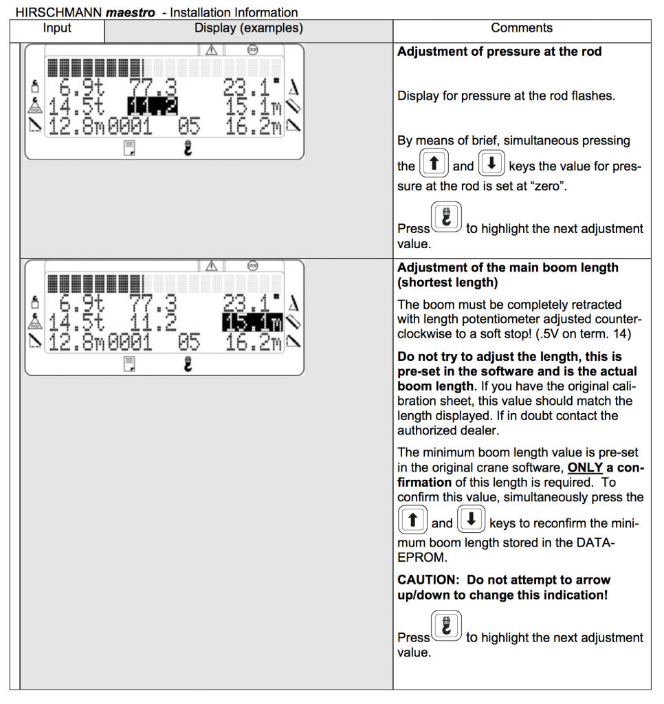
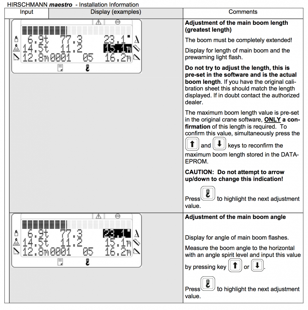
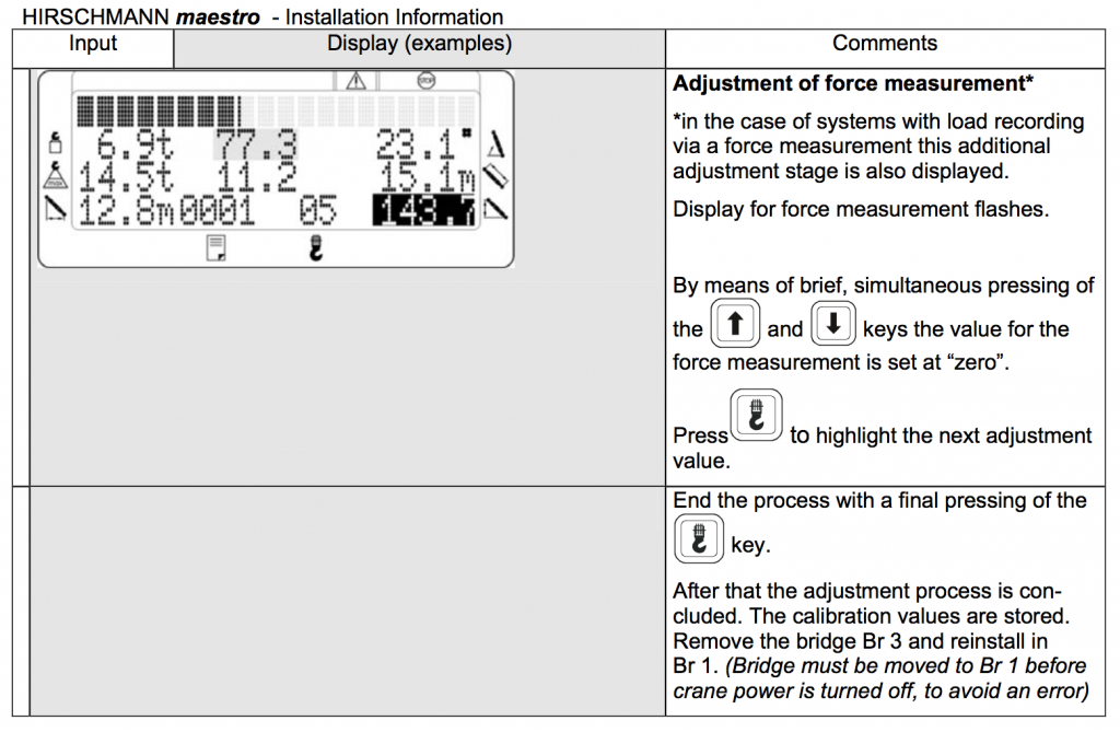
4 Hirschmann Maestro Start-Up Procedure
The start-up procedure of the new system is normally shortened a great deal in terms of time due to the transfer of the contents from the central processor memory and the automatic sensor adjustment. It is nevertheless necessary to check the contents of the data displays.
4.1 Checking the Data Display
Check the geometric data, which are shown on the display, by measuring for accuracy. If deviations arise, these can only be taken in hand by the inputting of correction values in the EEPROM. (Ref. 5.5 LMI test procedure) If necessary, you can use hand terminal to correct any data as usual for old PAT systems.
4.2 Final Tests
When all of the settings have been made, it is still necessary for the system to be checked, and load testing to be completed, in accordance with the manufacturer’s specifications. (Ref. 4.2.1 LMI Test Procedure)
4.2.1 LMI System Test Procedure

- Most crane manufacturer calibrate the cranes with the jib removed, it is recommended that this is done to carry out the following test. However on some cranes this might not be the case, if in doubt contact the manufacturer.
- For calibration verification, a test load is to be employed for each of the following configuration; NOTE: For safety reasons first measure the allowable radius for the load being used and have a spotter to ensure the system stops at or before this radius point.
- Maximum boom length and middle radius (select a load that will lock out the functions about the middle of the load chart in the long boom length step)
- The following test should be recorded signed and dated and a copy of this test sheet should be available at all times.
- Test load to be applied by suspending known weights accurate to +/-1%. Be sure weights of all additional equipment such as blocks, slings, sensors, etc., are included in the test load. The total load is to be known to an accuracy of +/-1%. With extended boom and the load suspended, move the load smoothly from the short radius to overload lock out, measure and record radius, calculate cut off % (See Section 6). Ensure the appropriate functions are disabled.
- Computations: For each radius measured in the above tests refer to the applicable load rating chart and determine the rated load. At radii intermediate to those on the load chart, rated load shall be determined by linear interpolation unless otherwise specified by the crane manufacturer.
- The system accuracy is to be determined from the following formula:
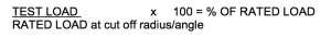
- The actual load which activates the overload lockout is not less than 90% of the rated load nor more than 100% of the rated load for the corresponding actual load radius or boom angle.
Note: This is a general standard and variations may exist, if in doubt contact the crane manufacturer.


These instructions based on Hirschmann Automation and Control GmbH • Mobile Machine Control Solutions • www.beldensolutions.com 031-300-190-196_L.Doc Hirschmann Maestro LMI System End User Installation Manual 04/27/07
Bode Technical Services Inc does not give any warranty for this material, including any implied warranty of marketability or fitness for a particular purpose. Bode Technical Services Inc is not liable for any errors in the contents of the material, or for any direct or indirect damage in connection with the provision and the use of this information.


