Linerider Settings & Adjustment Procedure
PAT – Hirschmann SKM Type
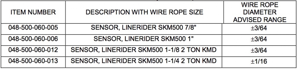
Calibration of a linerider will require the hoist rope line pull information, which should be provided by the manufacturer. Use single part line when calibrating the linerider. Lineriders require specific wire rope size, see table below to insure your rope size matches your linerider provided. Please note that a new wire rope is normally oversized, the amount of oversize will depend on the diameter of the rope. With normal wear the inter core breaks down and diameter decreases, See your manufactures guidelines for wire rope replacement conditions.
Important Note
These instructions assume fundamental knowledge of mechanical and electrical systems. Please make certain to follow the precise order of steps in the instructions. If you do not feel comfortable performing this procedure please contact one of the well qualified BTS Tech™ team members to assist you, toll free in the US at 855.BODE.TEC or internationally at +1.303.433.8878.
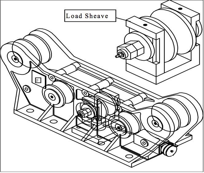
The linerider requires a load sheave adjustment to maximize the voltage output of the amplifier and minimize the line angle through the linerider. The linerider maximum output of 2.5 volts should be equal to the maximum hoist rope line pull. The load sheave may need to be adjusted by turning the eccentric wheel on the load sheave of the SKM500 linerider, see figure below.
LINERIDER ZERO POINT ADJUSTMENT
NOTE: Complete the following processes before placing cable through the linerider.
ZERO POINT SETTINGS
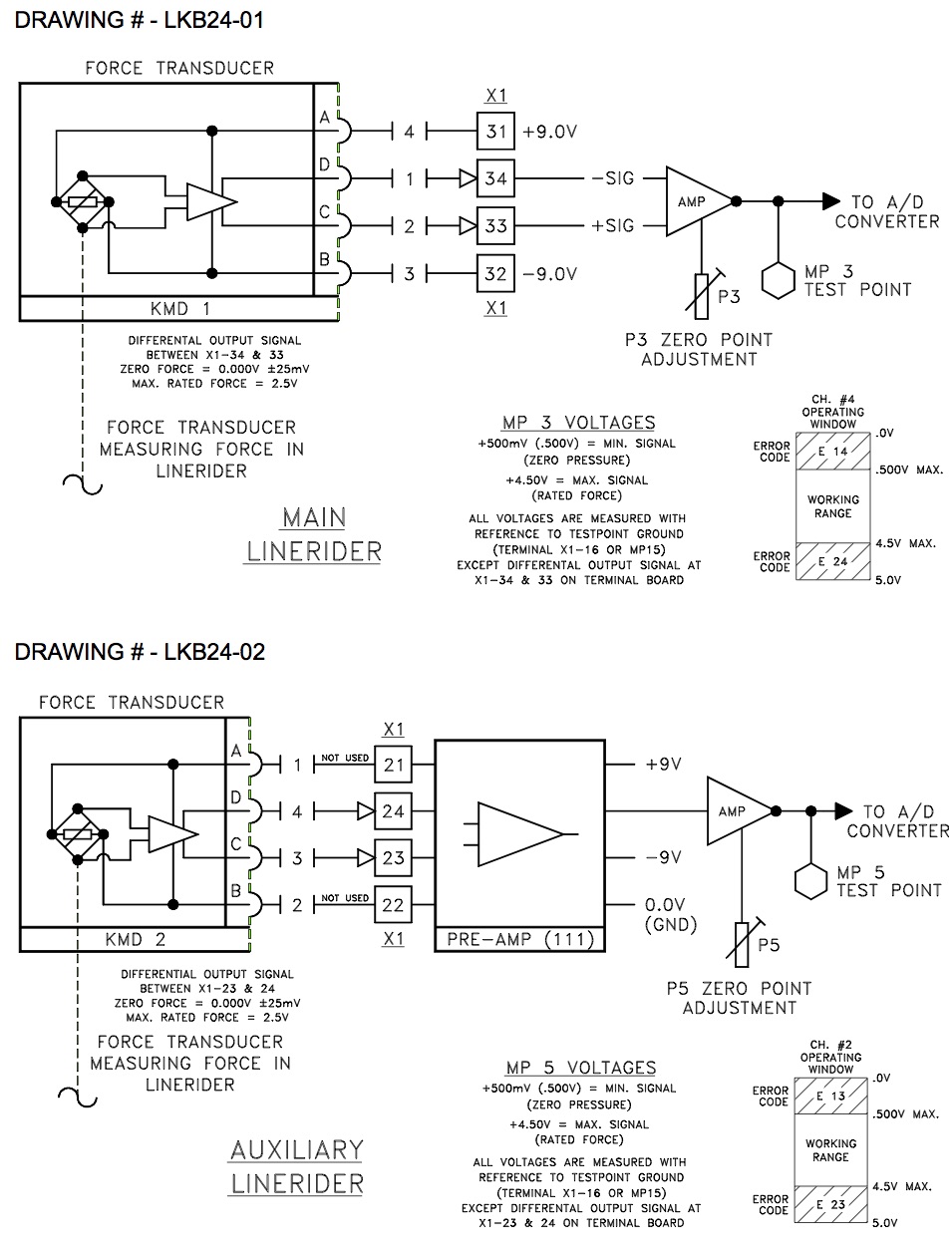
Check that the differential output of the main and auxiliary linerider is within ±25millivolts at zero force:
- Main Linerider: central unit terminal connection X1-#33 and X1-#34.
- Auxiliary linerider: central unit terminal connection X1-#23 and X1-#24.
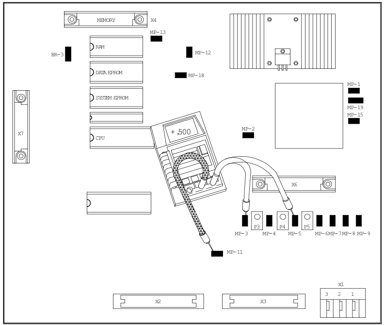
Adjust the linerider voltages on the main board, Refer to main board image below.
- Adjust the main linerider zero point by placing your positive volt meter lead on MP 3 (measuring point 3) with your ground lead on MP 11. Turn the screw on potentiometer P3 so the volt meter reads a value of 0.500 volts.
- Adjust the auxiliary linerider by placing your positive volt meter lead on MP 5 with your ground lead on MP 11. Turn the screw on potentiometer P5 so the volt meter reads a value of 0.500 volts.
- After completing this adjustment run the hoist rope through the lineriders.
LINERIDER OUTPUT ADJUSTMENTS
STEP 1 – Calculate the output voltage required from the linerider using the known the total load and maximum line pull information. The tolerance for the output voltage “X” is +0.0, -0.2 volts.
NOTE: The total load includes the load, rigging, cables, and hook block. Test load should be 80% of maximum rated load for the cranes configuration or condition. To comply with the SAE J376 standards the test load must be to a known accuracy of ±1%.
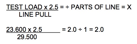
“X” is equal to the to optimum output voltage of the linerider. The output voltage required in this example is 1.8 to 2.0 volts.
WARNING: THE OPERATOR IS RESPONSIBLE FOR OPERATING THE CRANE WITHIN THE MANUFACTURE’S SPECIFIED PARAMETERS.
STEP 2 – Pick the test load used in the calculation for the output voltage with a single part of line.
STEP 3 – Take a voltage reading with a voltmeter and compare the reading with the calculated voltage and decide if a mechanical adjustment of the linerider is needed.
- Main Linerider: central unit terminal connection X1-#33 and X1-#34.
- Auxiliary linerider: central unit terminal connection X1-#23 and X1-#24.
STEP 4 – If a mechanical adjustment is necessary follow steps below, if no mechanical adjustment is necessary proceed to next Section and begin calibration.
- Before and after you set the mechanical adjustment, scribe a line on the side of the eccentric wheel to show the amount of change.
- Loosen the adjustment nut, see drawing below. Note that there is a single lockout nut on one side and a double on the other. These both should be loosened to some degree. Adjustment from the double nut side seems to work the best after tightening the 2 nuts together.
- Depending upon the output voltage you can look at the eccentric nut from the side of the linerider and determine the direction you should turn. Increasing the height of the load sheave will increase the output voltage.
- Tighten all lock nuts insuring not to move the wheel.
STEP 5 – Return and repeat “STEP 3.”
LINERIDER CANNON CONNECTION
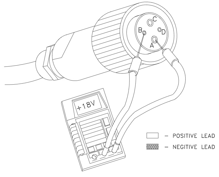
The supply voltage can be checked directly at the cannon connection. Using a digital volt meter measure between pins A and B, (A= + 9v) + (B= – 9v) = 18volts. If this voltage is not correct refer to the system wiring diagram and verify all cable connections. You may need to start at the main board and check the supply voltages at their proper measuring points.
NOTICE
All instructions based on PAT – Hirschmann DS 350 Troubleshooting Handbook 031-300-190-038 Revision D 12/05/05
The information on this webpage is subject to change without notice. Bode Technical Services Inc makes no warranty of any kind with regard to this material, including, but not limited to the implied warranties of merchantability and fitness for a particular purpose. Bode Technical Services Inc shall not be liable for errors contained herein or for incidental or consequential damages in connection with the furnishing, performance or use of this webpage.


