
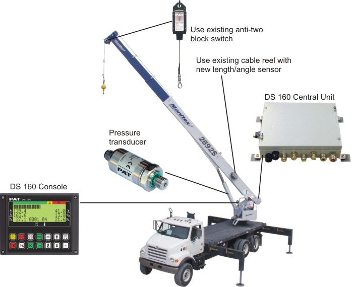
We are a global leader in the crane parts and service industry specializing in PAT DS50 troubleshooting and the sales of Hirschmann LMI systems including the DS50 to DS160 upgrade kit. If you need assistance with your aging PAT DS50 or information on the upgrade Hirschmann DS160 contact us toll free in the US at 855.BODE.TEC or internationally at +1.303.433.8878
DS50 Upgrade Brochure

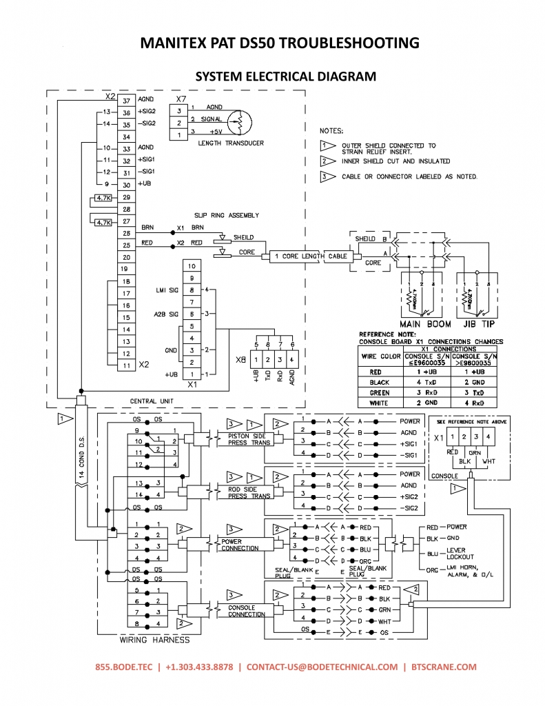
PAT DS50 TROUBLESHOOTING – Main Board Connection & Terminal Definitions
X1/X2 (fast-on plug)
- System supply (10 – 28V)
- System supply (10 – 28V)
- System ground
- System ground
- Relay middle contact
- Relay work contact
- Relay off position contact
- Jumper UEL / HES
- Jumper over load relay
- Jumper hoist limit switch relay
- Periphery supply (10 – 28V)
- Digital input_1
- Digital input_1
- Digital input_2
- Digital input_2
- Digital input_3
- Digital input_3
- Digital input_4
- Digital input_4
- Periphery ground
- Lamp driver_1
- Lamp driver_1
- Lamp driver_2
- Lamp driver_2
- Hoist limit switch signal
- Hoist limit switch ground
- Supply voltage potentiometric sensor
- 2ND angle sensor signal channel (analog reeving switch w/ MANITOWOC BOOM TRUCKS, INC. consoles)
- Analog ground
- Supply voltage passive DMS (9±0.45 VDC)
- – return signal DMS
- + return signal DMS
- Analog ground
- Supply voltage passive DMS (9±0.45 VDC)
- – return signal DMS
- + return signal DMS
- analog ground
X3 (DBM 9pin) RS232 interface for (hand-) terminal
X4 digital angle sensor
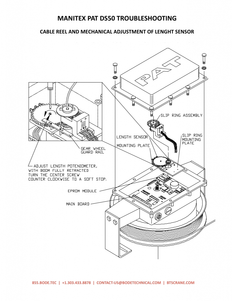
X7 (screw snap-on terminal) length sensor
- supply voltage potentiometric sensor
- length sensor signal
- analog ground
X8 (screw snap-on terminal) DS50 console interface
- periphery supply (10 – 28V)
- transmit data
- receive data
- periphery ground
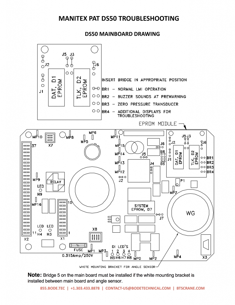
Main Board Measuring Points
MPO 0V
MP1 +10 … 28V
MP2 +9V ±0.45V
MP3 +5V ±0.25V
MP4 UTTL
MP5 UGEB/2
MP6 UGEB/2
MP7 0 … UTTL
MP8 UTTL/2
MP9 UTTL
MP10 UDMS/2
MP11 UANAL
MP12 0V…5V
MP13 0V…5V
MP14 UDMS/3
MP15 2.74V+UD
MP16
module ground
module supply
sensor supply
sensor supply
supply for hand terminal
AN3 / angle sensor
AN2 / length sensor
voltage controlled current output (UTIL=1mA)
AN11
sensor supply
symmetric voltage for de-coupling DMS – supply voltage
AN0
AN1
AN9
AN8 / temperature voltage
A2B signal


