LSI MBR100 & 105 CRANE INDICATOR USER MANUAL
1. General LSI MBR100 Handheld Display Information
all information copyright Trimble Lifting Solutions LTD manual: “MBR100 Handheld Display Installation and Operation Manual GM100_ENG_rev1.1”
1.1 Introduction
The MBR100 is explained as follows: The system includes the handheld MBR100 radio display and compatible Trimble Lifting Solutions sensors. The MBR100 creates a two-way radio network with the sensors to bring required data to the operator. The MBR100 has a user-adjustable limit and will generate an alarm when this
limit is reached.
1.2 About This Manual
This installation and operation manual describes how to install, operate and maintain the MBR100.
1.2a Notifications Included in Document
The following notations may be used in this manual:
1.2b How To Provide Feedback To Trimble Lifting Solutions
Trimble Lifting Solutions welcomes your feedback on the accuracy and effectiveness of this document.
Please send feedback to TLS_doc@trimble.com. Please include the title of the manual and version with your feedback.
1.2c How This Manual Is Updated
Trimble Lifting Solutions will issue new releases of this manual as new material becomes available.
1.2d How to Contact Trimble Lifting Solutions
Please contact Trimble Lifting Solutions if you encounter problems or require advice. Contact details are located on the back cover.
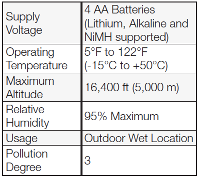
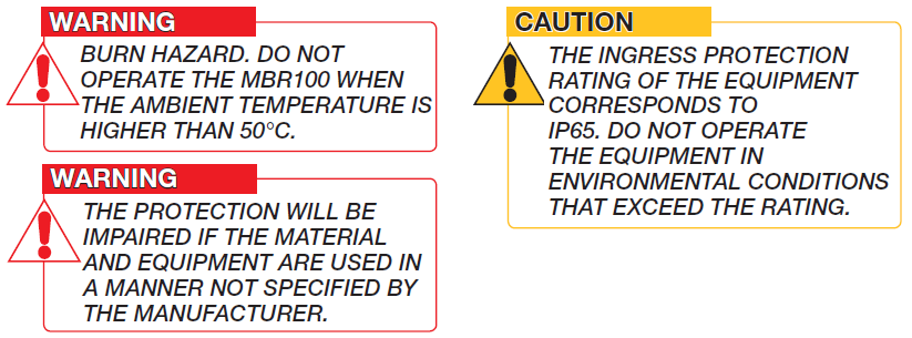
1.3 Recommended Operating Conditions
1.4 Powering Up
On power up, the display will show six horizontal lines and the antenna symbol will flash. Once a reliable radio communication network is established, the antenna symbol will remain lit without flashing. If the antenna symbol flashes continuously, the MBR100 may not be correctly programmed. To correctly program the MBR100, follow the How to Add a Sensor procedure on Section 4.3.
1.5 Before You Begin
2. ANTENNA, BATTERY AND CLEANING OVERVIEW
2.1 Antenna Position
The LSI MBR100 handheld display antenna is located in the lid. For optimal performance, the LSI MBR100 handheld display should be used with the lid
fully open to 180°.
1. The antenna should have 5 inches (127 mm) of clear space all around it. The RAM mount is approximately 4 inches (102 mm).
2. The antenna should have an unobstructed line of sight with the sensor.
2.2 Battery Information
The LSI MBR100 handheld display operates with 4 AA batteries.
Three types of batteries are supported: alkaline, NiMH (Nickel-Metal Hydride) or lithium 1.5V.
The rechargeable batteries must be charged outside of the display.
2.3 Battery Replacement
1. Unscrew the four screws.
2. Remove battery cover.
3. Remove the batteries by hand.
4. Install the new batteries (insert the positive end, then push in the direction of the positive pole).
5. Reposition the battery cover and tighten the four screws. Do not over-tighten.
2.4 Cleaning Instructions
To clean the device, wipe it with a clean dry cloth. Use caution when wiping the display area. The material can scratch easily.
You may use a mild soap and water solution on a damp microfiber cloth to clean outer surfaces (do not immerse in water).
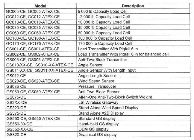
2.5 Supported Sensor Type
GC Load Cells, GLC Load Cells, GS001-XX, GS010-XX, GS020, GS026, GS005, GS075-B, PT00100-XX, GS110 (Angle only), GS112 (Angle only), GS007-XX (Line Rider Tx/Rx).
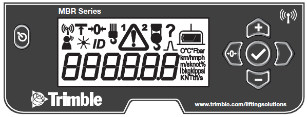
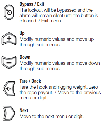
3. BUTTON AND ICON DEFINITION
3.1 Button Definition
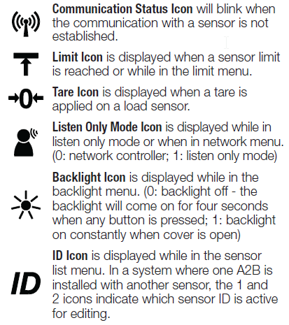
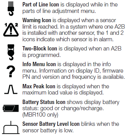
3.2 Icon Definition
4. DISPLAY AND MENU OVERVIEW
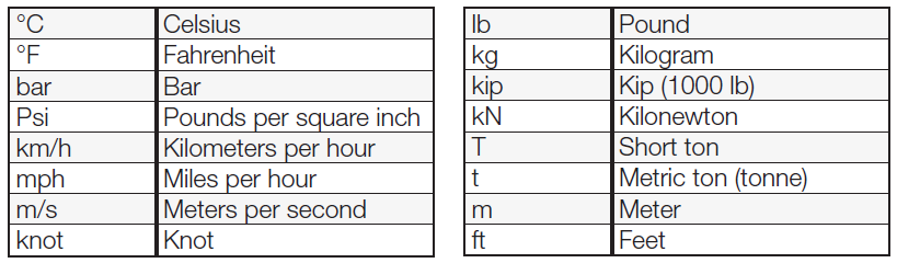
4.1 Display Abbreviations
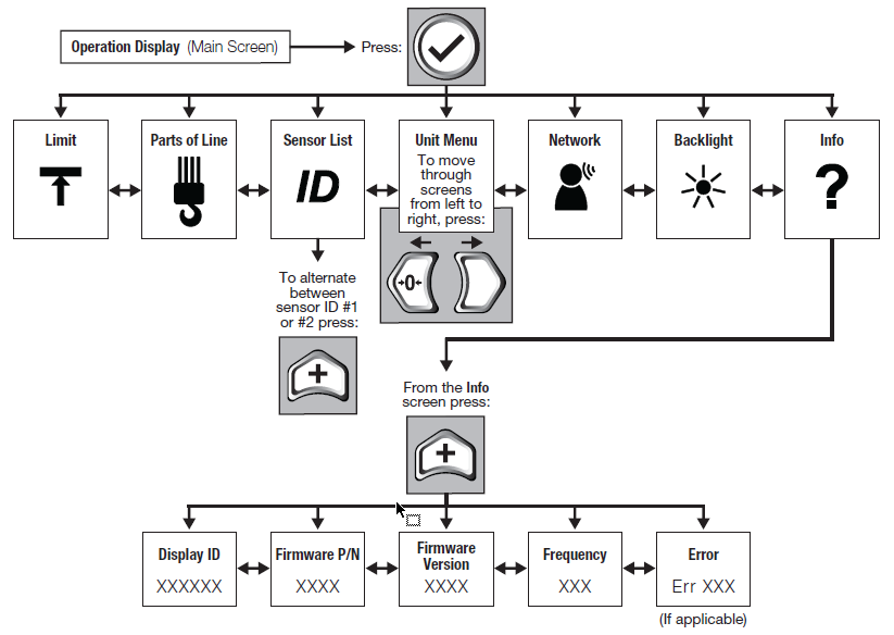
4.2 Menu Outline
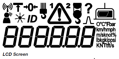
4.3 Symbol Overview
1. Communication Status

The communication status icon appears when a sensor is programmed in the MBR100. The icon stays on when the LSI MBR100 handheld display has a reliable radio communication link to all programmed sensors. The icon blinks when communication with any programmed sensor is not established.
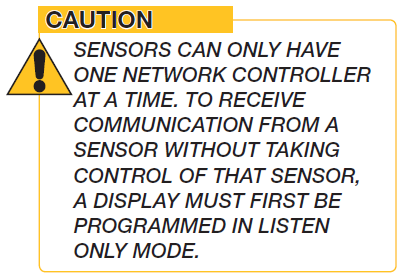
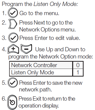
2. Network Options

Network Controller when the LSI MBR100 Handheld Display is powered up it normally wakes up all sensors programmed in the sensor list and takes control of them. If a second display is powered up with one or more of the same sensors programmed in the sensor list, then the second display will take control of those sensors; the sensors will no longer acknowledge communication from the first display. Listen Only Mode When the MBR100 is programmed to operate in listen only mode, it displays the information from programmed sensors without becoming the network controller.
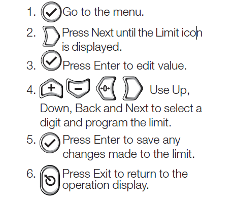
![]() To change the limit of a programmed sensor:
To change the limit of a programmed sensor:
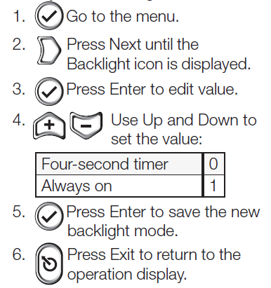
4. Backlight Mode
![]() The LCD backlight can be always on, or on a four-second timer, following a keypad entry. To adjust the backlight mode:
The LCD backlight can be always on, or on a four-second timer, following a keypad entry. To adjust the backlight mode:
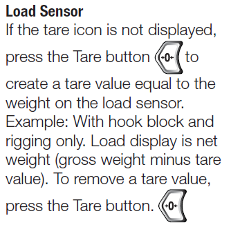
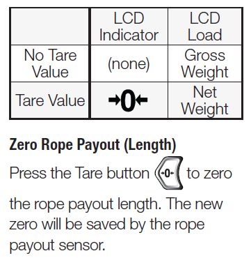
5. Tare
 Tare is used to zero the hook and rigging weight on a load sensor or to zero the rope payout value.
6. 6. 6. 6.
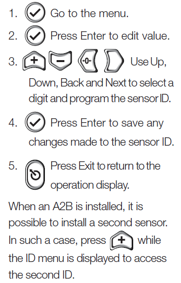
6. ID
![]() The sensor in the LSI MBR100 Handheld Display system is programmed in the ID menu. To add a sensor:
The sensor in the LSI MBR100 Handheld Display system is programmed in the ID menu. To add a sensor:
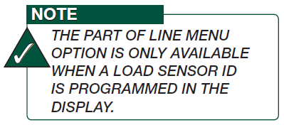
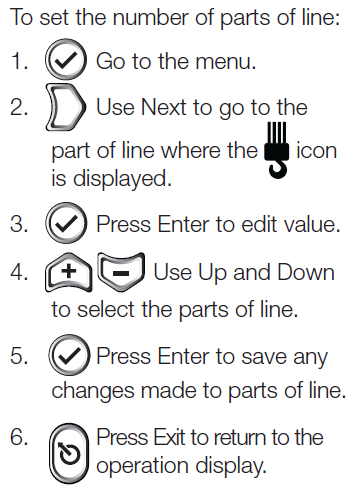
7. Part of Line
![]() The load sensor often shares the weight with multiple parts of line. For accurate load indication the MBR100 must be programmed for the number of parts of line.
The load sensor often shares the weight with multiple parts of line. For accurate load indication the MBR100 must be programmed for the number of parts of line.
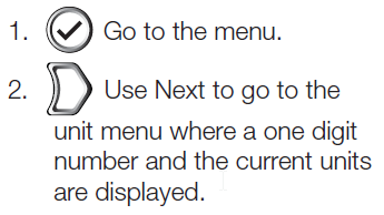
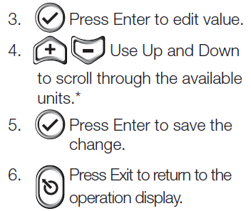
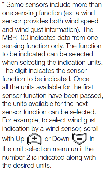
8. Unit and Sensor Function Selection
To change the sensor unit or to change the sensor function, the LSI MBR100 Handheld Display must be in communication with the sensor programmed.
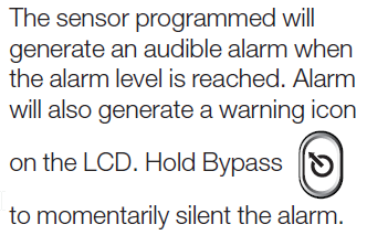
9. Alarm

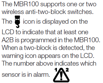
10. A2B
![]()
11. Information
![]()
Standard Info menu pages include:
1. Display ID
2. Firmware Number
3. Firmware Version
4. Display Frequency
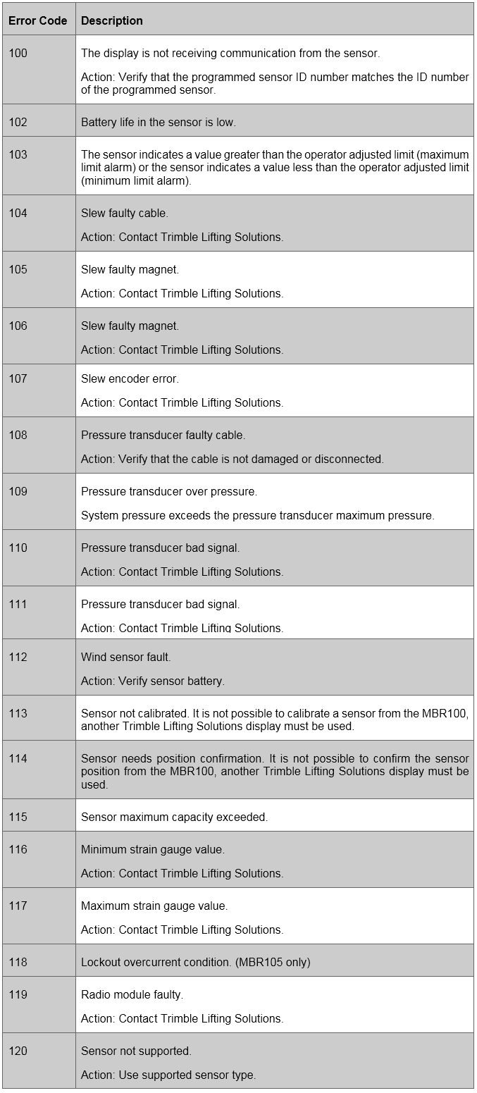
5. Error Code(s) – If Applicable
List of possible error codes:
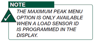
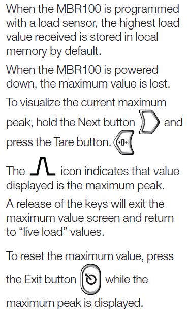
12. Maximum Peak
![]()
13. Low Sensor Battery

The sensor icon flashes when one of the programmed sensors’ battery life is low.
5. CERTIFICATION NOTES
5.1 FCC and IC—Instructions to the User
This equipment has been tested and found to comply with the limits for a class B digital device, pursuant to part 15 of the FCC Rules. These limits are designed to provide reasonable protection against harmful interference in a residential installation. This equipment generates, uses, and can radiate radio frequency energy and if not installed and used in accordance with the instructions, may cause harmful interference to radio communications. However, there is no guarantee that interference will not occur in a particular installation. If this equipment does cause harmful interference to radio or television reception, which can be determined by turning the equipment off and on, the user is encouraged to try to correct the interference by one or more of the following measures:
• Reorient or relocate the receiving antenna.
• Increase the separation between the equipment and receiver.
• Connect the equipment into an outlet on a circuit different from that to which the receiver is connected.
• Consult the dealer or an experienced radio/TV technician for help.
FCC ID: QVBMBR001
IC: 7076A-ICMBR001
RF Exposure Warning:
The MBR100 complies with FCC/IC radiation exposure limits set forth for an uncontrolled environment. To comply with RF exposure requirements, the unit must be installed and operated with 0.8 in (2 cm) or more between the antenna (located inside the lid) and your body. This product may not be collocated or operated in conjunction with any other antenna or transmitter.
This device complies with Industry Canada licence-exempt RSS standard(s). Operation is subject to the following two conditions: (1) this device may not cause interference, and (2) this device must accept any interference, including interference that may cause undesired operation of the device. Changes or modifications not expressly approved by the party responsible for compliance could void the user’s authority to operate the equipment.
FCC ID: QVBGS000
IC: 7076A-ICGS000
RF Exposure Warning:
Trimble Lifting Solutions sensors comply with FCC/IC radiation exposure limits set forth for an uncontrolled environment. To comply with RF exposure requirements, the unit must be installed and operated with 8 in (20 cm) or more between the product and your body. This product may not be collocated or operated in conjunction with any other antenna or transmitter.
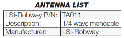
This device has been designed to operate with the antennas listed below, and having a maximum gain of 3.0 dB. Antennas not included in this list or having a gain greater than 3.0 dB are strictly prohibited for use with this device. The required antenna impedance is 50 ohms.
To reduce potential radio interference to other users, the antenna type and its gain should be so chosen that the equivalent isotropically radiated power (e.i.r.p.) is not more than that permitted for successful communication.
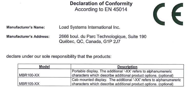
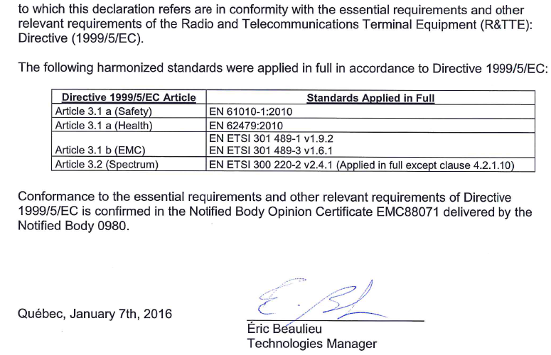
5.2 CE
5.2a Declaration of Conformity

5.2b CE Safety
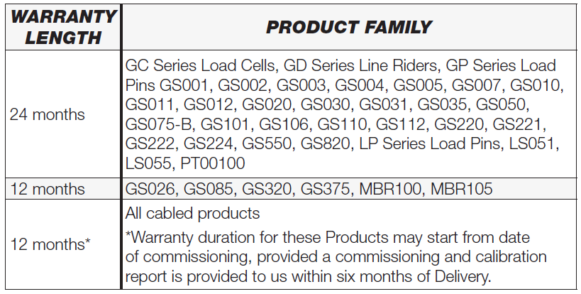
6. LIMITED WARRANTY
Please note that the Products are not intended for use in pile driving, wire rope activated clamshell or dragline applications, and any such use will be considered misuse of the Product and will exclude the Product from warranty coverage.
In connection with this limited warranty, we may require that we receive the data logging equipment used with the Products. You hereby authorize us to retrieve all information from such data logging equipment, which we may use, for example, in order to confirm compliance with written instructions and applicable standards, including safety margins. If we do not receive such information as requested, we shall have no obligations under this limited warranty. Costs associated with providing us with data logging equipment shall be borne by you.
If you request and we agree to provide attendance on site, you will pay our current applicable service rate for time on site, along with travel time from the nearest service center with the requisite capabilities, and fares and expenses.
In the event a Product is determined to be covered by this limited warranty, we will pay ground freight shipping fees of replacement or repaired parts or Products to the destination in the countries in which we maintain a service center for the applicable Products (currently Canada, continental United States of America, United Kingdom, Australia and the United Arab Emirates), but shipping fees for any other destination will be borne by you.
Detailed terms of the warranty are set forth at http://www.trimble.com/support/ terms_of_sale.aspx, subject to the
additional terms set forth above.


