HIRSCHMANN DISPLAY REPLACEMENT INSTRUCTIONS

We are a leading provider of PAT Hirschmann and Krueger crane parts on a global scale. With 38 years of industry experience, and thousands of customers across the world, you can trust that our parts team can supply you with fast service, cost effective parts, and exceptional knowledge anywhere in the world. If you need help with your Hirschmann display, contact us toll free in the US at 855.BODE.TEC or internationally at +1.303.433.8878
Hirschmann Display Installation Overview
050-350-061-351 / 050-350-061-354
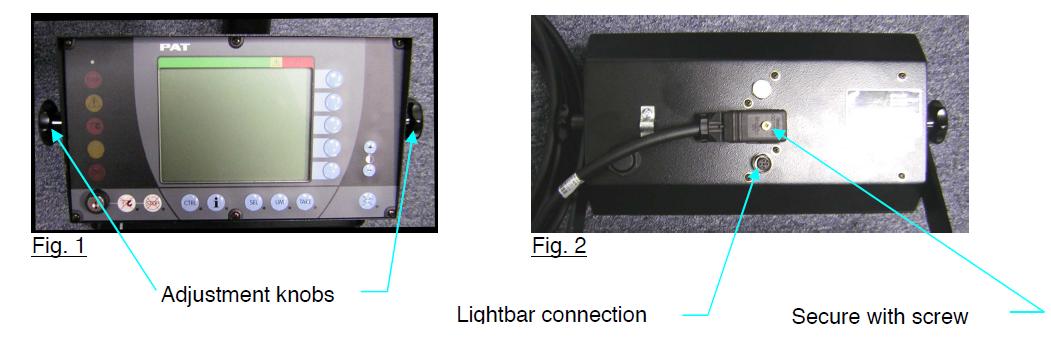
Remove existing console at the adjustment knobs. (Fig. 1)
- Install new Hirschmann display on the dash using the existing mounting bracket.
- Connect and fix the connector on console cable assy 031-300-060-598 to the console. (Fig. 2)
- Route console cable assy to the central unit following the same path as the existing console cable
assy. - Refer to appropriate Central Unit section for further installation instructions.
- Cable Assembly 031-300-060-520 will be required for installation of the lightbar option currently installed on the DS350GW horizontal and vertical consoles.
050-350-061-351 / 050-350-061-354
NOTE:
Cable Assembly 031-300-060-520 will be required for installation of the lightbar option currently installed on the DS350GW horizontal and vertical consoles.
HIRSCHMANN DISPLAY INSTALLATION OVERVIEW
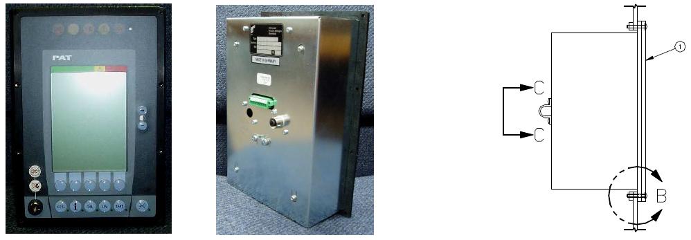
050-350-061-189 / 050-350-061-355
- Remove existing Hirschmann display, console wiring, and housing. Note: The existing wiring will be used to wire the new console.
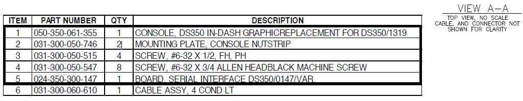
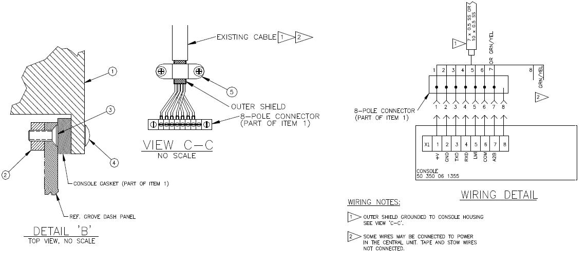
- Install (2) console nut strips item 2 using (4) screws item 3 through the existing countersunk holes in dash per Detail “B”.
- Install new console with housing in tact. Secure to nut strips item 2 with (8) screws item 4 per Detail “B”.
- secure existing cable with clamp (part of console) per View C-C. Be sure the cable’s outer shield is in contact with the clamp.
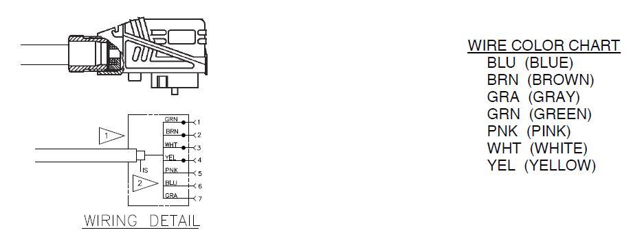
- wire the 8-pole connector on the rear of the console per the wiring diagram. Ref. View C-C.
HIRSCHMANN CENTRAL UNIT
DS350GM (24 350 06 300x)
System Software Installation Overview
-
- Remove C.U. lid.
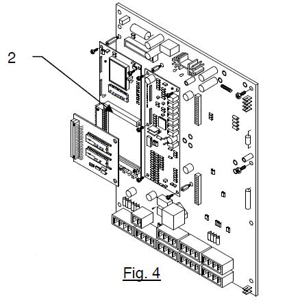
- Check the system software version. If it is NOT a CGMT version,(label says CGMT Vx.x) remove it and replace with (GGMT V2.0) system software eprom. (Fig.4) (For further eprom replacement instructions see Procedure1 below.)
Procedure 1. EPROM REPLACEMENT
Remove cover, from central unit.
-
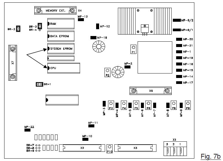
- Refer to the drawing below for correct eprom locations. (Fig.4a)
- Remove the old system eprom, from the main board. Be careful to pull the eprom out
without bending the legs.
NOTE: Ensure the notch is in the correct direction. Notch on eprom must match the notch on the socket and markings on the board. - Place new eprom in the correct eprom socket as shown. Carefully align the new eprom legs with the socket and push the eprom into place. Be careful not to bend any of the legs.
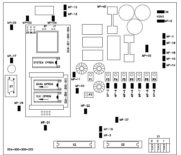
Fig.4a
Procedure 2. Strain Relief Installation
-
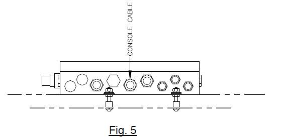
- Remove existing cable, ferrite filter and strain relief from central unit. (Fig. 5)
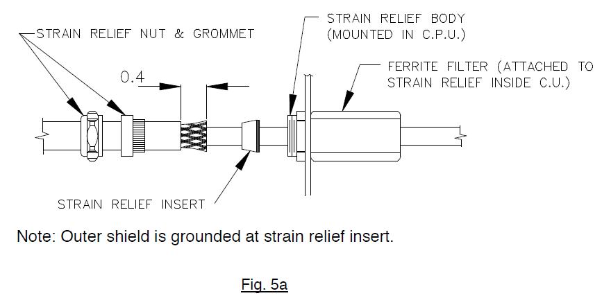
- Install the new PG13.5 RED/WHT strain relief using the existing PG13.5 nut, from the strain relief just removed.
- Reinstall ferrite filter. (Fig. 5a).
Procedure 3. Console Cable Installation In Central Unit
-
- Ensure console is properly installed in cab.
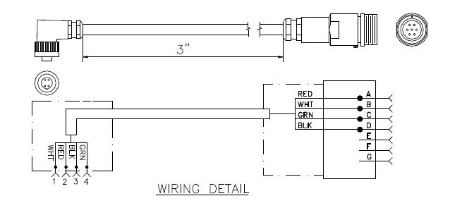
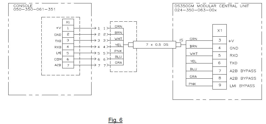
- Route console cable assembly (031-300-060-598) to the central unit following the same path as the existing console cable assembly. Cut the console cable to the appropriate length.
- Wire the console cable assembly in central unit referencing the diagram. (Fig. 6)
- Install the C.U. lid. Reinstall and any grounding wires removed, then install the cover and tighten screws, making sure the rubber gasket, is positioned correctly, to prevent any moisture from entering the central unit.
CENTRAL UNIT
DS350G ( 24 350 06 0700, 24 350 06 0701, 24 350 06 0721, 24 350 06 2766)
System Software Replacement For DS350G
-
- Remove cover, from central unit.
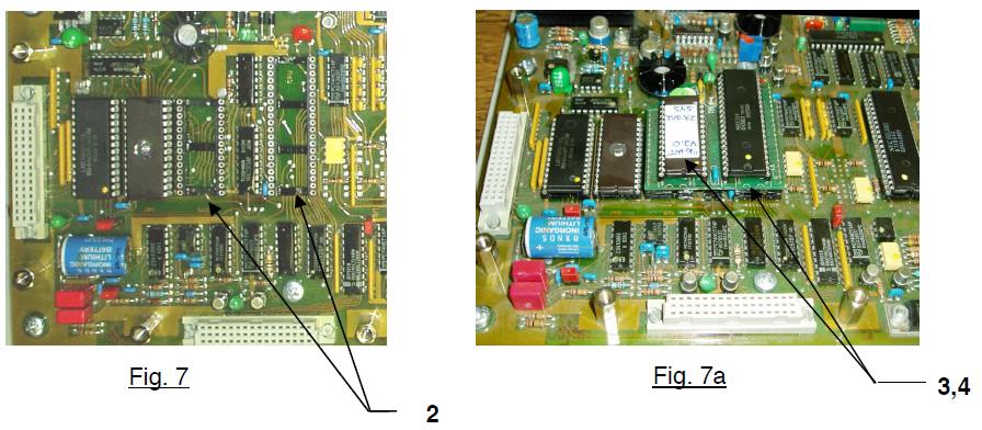
CAUTION: Before handling the EPROM, discharge any static electricity from your body by touching a grounded point. The EPROM could be damaged by static electricity. - Remove the existing system and CPU eproms from the main board. (Fig. 7) Be careful to pull the EPROM out, without bending the legs.
- Install eprom module 024-350-300-172 into the CPU and system software sockets. (Fig. 7a)
Replace the CPU and new system software (MGWT) eprom into the eprom module.
NOTE: The notch on the EPROM and in the socket determines the correct orientation of the EPROM. Refer to the drawing below for correct EPROM locations. - Carefully align the new EPROM legs with the socket and push the EPROM into place. Be careful not to bend any of the legs.
- Remove cover, from central unit.
Serial Interface installation
-
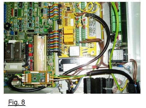
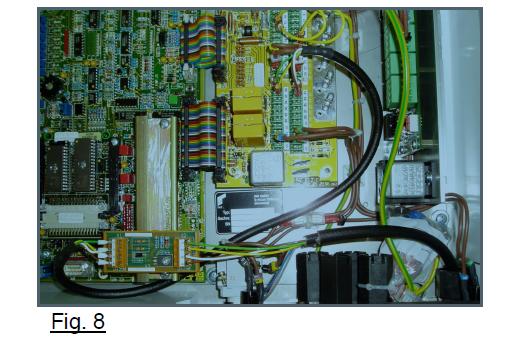
- Locate position of installation. (Fig. 8)
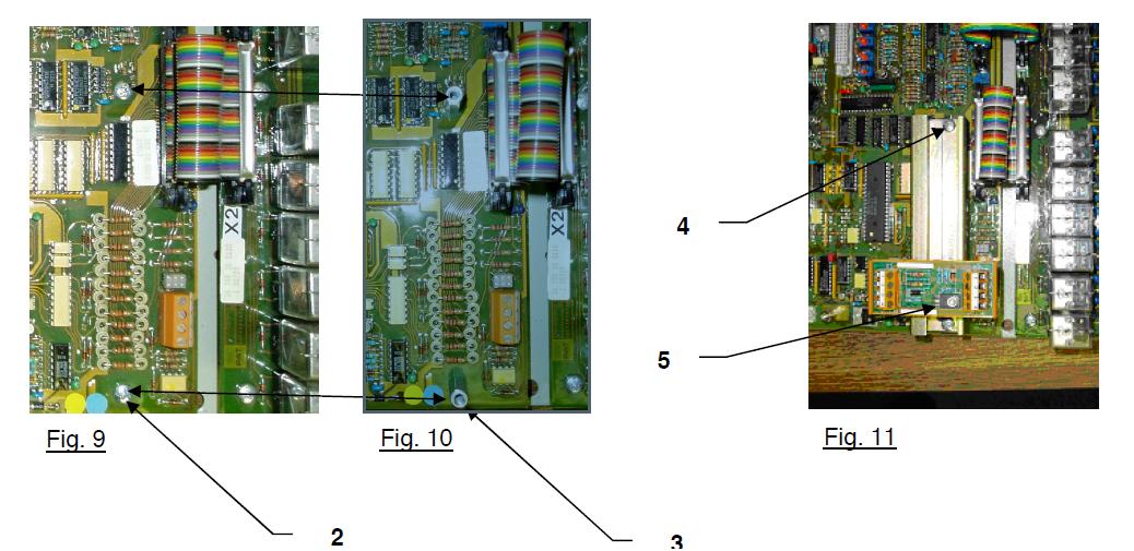
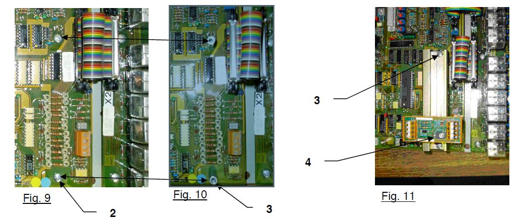
- Remove two screws and lock washers from the main board. (Fig. 9)
- Install two 4mm x 20mm standoffs where the screws were removed. (Fig. 10)
- Attach mounting rail 031-300-050-721 on top
of the standoffs using the screws and lock washers removed from the main board. (Fig.11) - Install (snap) serial interface board 024-350-300-147 on the mounting rail. (Fig.11)
-
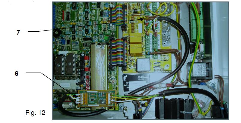
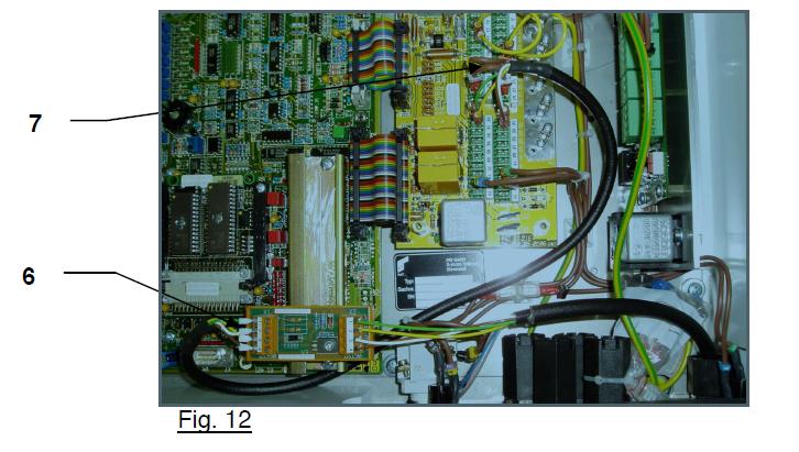
- Wire cable assy 031-300-060-610 (crimp ferrule end) to terminal X1 on the serial interface board per the electrical schematic. (Fig. 12 and 15, 15a)
- Wire the other end of the cable (1/8” female terminal end) to the connection board per the electrical schematic. (Fig. 12 and 15, 15a, 15b)
HIRSCHMAN DISPLAY CENTRAL UNIT PREPARATION
(Not required when replacing the 050-350-061-189 console). Do not remove existing cable between console and central unit for installation of the 050-350-061-355 console.
-
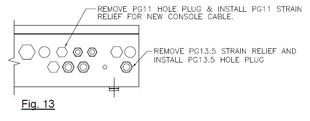
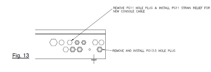
- Remove existing console cable and strain relief from the central unit and install PG13.5 hole plug using the existing nut. Remove existing PG11 hole plug. Install new PG11 strain relief using the existing nut. (Fig. 13). For 24 350 06 2766 central unit secure the PG11 stain relief with PG13.5-11 reducer and transfer the ferrite filter from the removed PG13.5 strain relief to the PG11 strain relief. Reference Fig. 5a.
Cable Assembly Installation (24 350 06 2766 only)
-
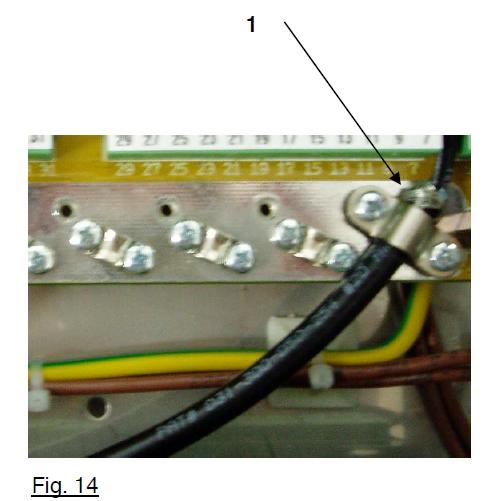
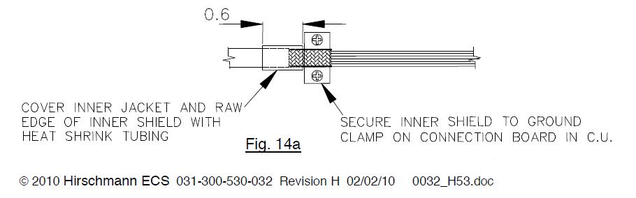
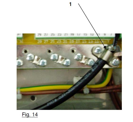
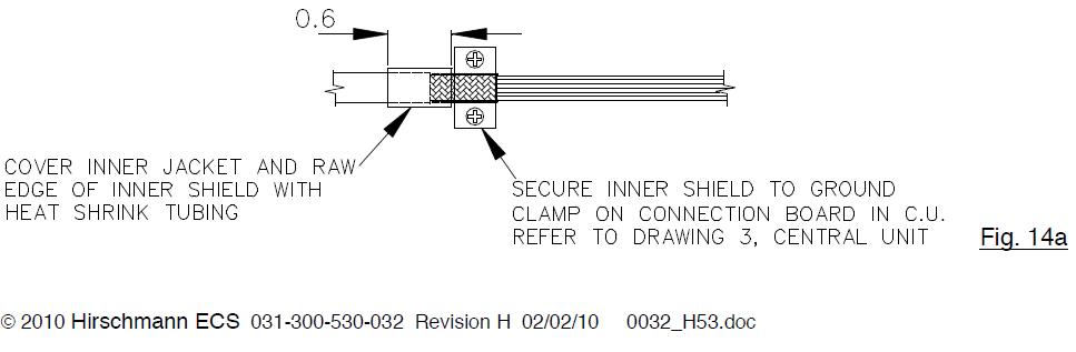
- Attach inner shield to grounding clamp on the connection board per diagram. (Fig. 14 and 14a)
- Install 1/8” and ¼” female terminals on wire ends and attach to connection board and diode assy per electrical schematic. (Fig. 15)
- Reinstall central unit lid and any grounding wires that were removed.
Grounding of Inner Shield (24 350 06 2766 only)
Inner shield is grounded on connection board.
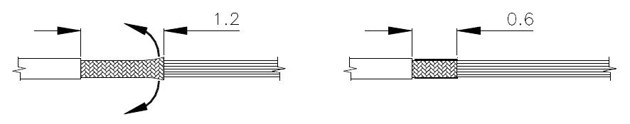
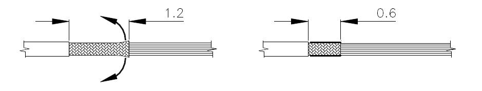
Cut inner shield back to approximately 1.2 inch. Then fold inner shield back to inner jacket, so the inner shield is 0.6 inches in length.
DS350G Central Unit Wiring (24 350 06 2700, 2766)
PAT DS350G Central Unit Wiring (24 350 06 0701, 24 350 06 0721)
PAT DS350G Central Unit Wiring (24 350 06 0700)
PAT HIRSCHMANN CENTRAL UNIT
DS350GC (24 350 06 2767)
Serial Interface Installation
-
- Locate position of installation. (Fig. 8)
- Remove two screws and lock washers from the main board. (Fig. 9)
- Install two 4mm x 20mm standoffs where the screw were removed. (Fig. 10)
- Attach mounting rail 031-300-050-721 on top of the standoffs using the screws and lock washers removed from the main board. (Fig. 11)
- Install (snap) serial interface board 024-350-300-147 on the mounting rail. (Fig. 11)
-
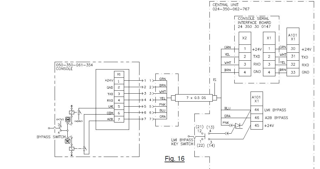
- Wire cable ass’y 031-300-060-610 (crimp ferrule end) to terminal X1 on the serial interface board per the electrical schematic. (Fig. 12 and 16)
- Wire the other end of the cable (1/8” female terminal end) to the connection board per the electrical schematic. (Fig. 12 and 16)
Hirschmann Central Unit Preparation
-
- Remove existing console cable and strain relief from the central unit and install PG13.5 hole plug using the existing nut. Remove existing PG11 hole plug. Install new PG11 strain relief using the existing nut. (Fig. 13)
Cable Assembly Installation
-
- Attach inner shield to grounding clamp on the connection board per diagram. (Fig. 14 and 14a)
- Install 1/8” and ¼” female terminals on wire ends and attach to connection board and diode ass’y per electrical schematic. (Fig. 16)
- Reinstall central unit lid and any grounding wires that apply.
Grounding of Inner Shield
-
- Inner shield is grounded on connection board.
-
- Cut inner shield back to approximately 1.2 inch. Then fold inner shield back to inner jacket, so the inner shield is 0.6 inches in length
DS350G Central Unit Wiring (24 350 06 2767)
PAT HIRSCHMANN CENTRAL UNIT
DS350GM (24 350 06 3015)
Procedure 1. Strain Relief Installation
- Remove cover from the central unit. Remove ground and heater wires as required.
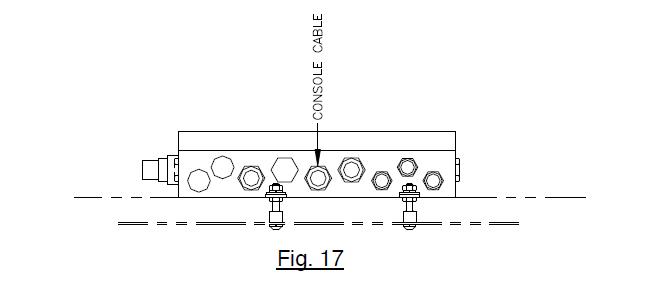
- Remove existing cable and strain relief grommet from the central unit. Do not remove the
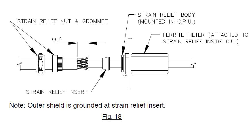
strain relief. (Fig. 17) - Install the new strain relief grommet only, and install console cable. (Fig. 18).
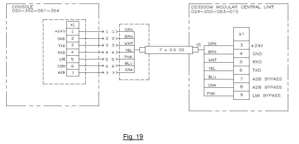
Procedure 2. Console Cable Installation In Central Unit
- Ensure Hirschmann display is properly installed in cab.
- Route console cable assembly (031-300-060-697) to the central unit following the same path as the existing console cable assembly. Cut the Hirschmann display console cable to the appropriate length.
- Wire the console cable assembly in central unit referencing the diagram. (Fig. 19)
- Install the C.U. lid. Reinstall and any grounding and heater wires removed, then install the cover and tighten screws, making sure the rubber gasket, is positioned correctly, to prevent any moisture from entering the central unit.
REQUIRED TOOL LIST
1 – #1 PHILLIPS HEAD SCREWDRIVERS
1 – ¼” SLOTTED HEAD SCREWDRIVERS
1 – ADJUSTABLE WRENCH
1 – WIRE CUTTERS
1 – VICE GRIP PLIERS
1 – ROLL INSULATION TAPE
1 – NEEDLE NOSE PLIERS
1 – WIRE CRIMPING PLIERS
1 – UTILITY KNIFE
1 – EPROM PULLER