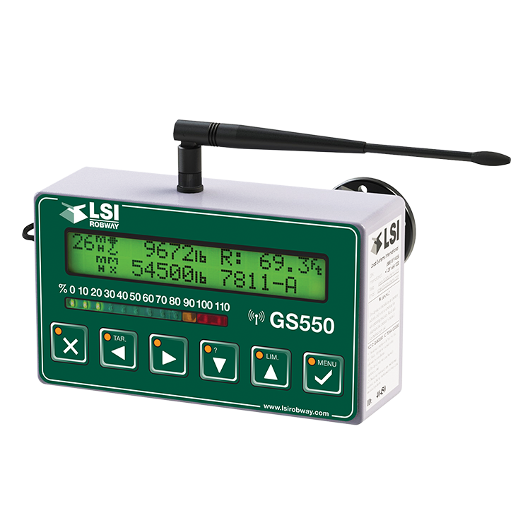
GS550 Display & GS Series Sensors
Installation & Users Manual


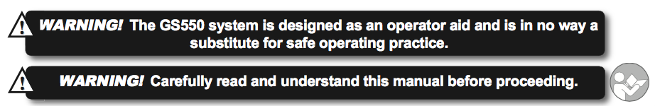
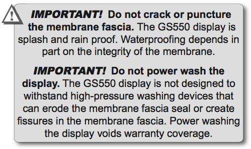
Before proceeding read and understand the following:
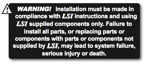
For your safety and that of the people that come into contact with LSI products, understand the significance of the instructions included in this guide, respect all laws and regulations and comply with applicable standards. Pay particular attention to items bearing the alert symbol:
![]() 

and the following words:
![]()
Important: this denotes an instruction that if not complied with may lead to product performance issues.
GS550 WIRELESS CRANE DISPLAY INSTALLATION
1.1 Overview
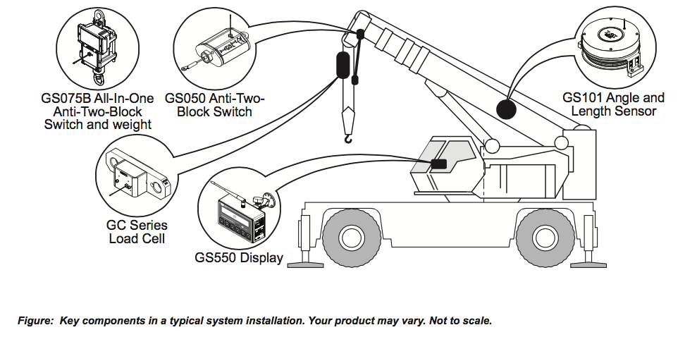
The GS550 system includes the cabin mounted GS550 radio display and compatible crane mounted sensors. The GS550 creates a two-way radio network with the sensors to bring required lift data to the operator. Hoist load, boom and jib angles, boom length, wind speed and pending two- block can be detected and then indicated to the operator in real time. Working load radius can be calculated and compared to a rated capacity chart (if programmed). Furthermore the GS550 can be programmed to generate warnings, alarms and lockout commands, all triggered by adjustable thresholds and limits. All these events can be recorded by the data logger with a time and date stamp. The exact operational function of the GS550 system depends on the sensor configuration used and the rated capacity charts programmed (where applicable). The GS550 includes a USB port to facilitate software and chart updates and data logger downloads using a USB mass storage device (USB key).
1.2 Start-Up
The GS550 must be correctly programmed for the system sensors installed. Once a reliable radio communication network is established, the display lights will remain lit without flashing. If a sensor is missing or has a problem, the Info button light will flash. Press the Info button to get more details on the problem. This process may take up to one minute. The delay is created by the battery management function. Press Bypass/Exit to temporarily bypass crane function lockout caused by a missing sensor. If rigging requires a crane configuration outside of the limits defined by the rated capacity chart selected, out of chart alarms can be avoided by placing the the display in “rig mode”. If the rig mode is enabled in the display, press Bypass/Exit for 10 seconds to activate it. If the rig mode is not available, contact your LSI representative or LSI technical support representative.
GS550 INSTALLATION
NOTE: REFER TO OPRATION SECTION FOR DETAILED MENU NAVIGATION INSTRUCTION FOR ALL CALIBRATION PROCEDURES

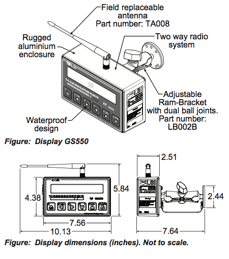
2.1 Display GS550
2.1a Mounting Bracket
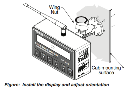
1. Begin the GS550 wireless crane display installation by determining the mounting location; the display may be installed either inside or outside the cab. It can be mounted on the dash, on a sidewall, or on the ceiling of the cab. To ensure reliable radio communication between sensors and the GS550, the antenna should not be in contact with metal and should have a direct and clear line of sight to the sensor antenna. The mounting bracket requires a flat surface of at least 2.5 inches in diameter on both sides and where the back of the surface is accessible in order to tighten the nuts.
2. Drill 1/4 inch boltholes through the mounting surface with a 1/4 inch bit following either the two, three, or the four holes configuration.
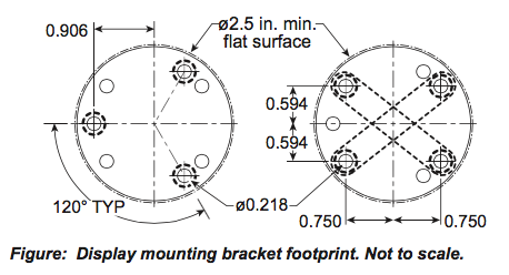
3. Install the display with bolts. Add washers and lock nut behind the mounting surface and tighten sufficiently (bolts, nuts and washers not included). Note: If the nuts are on the outside of the cab, caulk with silicone between the washers and the cab to prevent water entry.
4. Loosen the wing nut of the bracket arm to adjust display orientation to facilitate viewing by the operator and then tighten it back up.
2.1b Antenna Position
For optimal performance the antenna should be positioned on its side such that it is parallel to the sensor antennas (but not pointing directly to or directly away from them)
- Adjust the antenna position with the articulating base.
- The antenna should have 5 inches of clear space all around it.
- The antenna should have an unobstructed line of sight to all sensor antennas at all boom angles.
2.1c Power Supply and Lockout Connection
1. Connect the black wire (ground) to the negative terminal of the battery or the panel connection; alternatively bolt the black wire to the body of the machine with a 1/4 inch or 5/16 inch bolt. The ground connection must be strong enough to sustain 3 amperes.
2. Connect the red wire to a fused accessory source, rated at least 3 amperes, that supplies +12 or +24 volts when the machine is in use. The GS550 will automatically detect the voltage level and adjust itself.
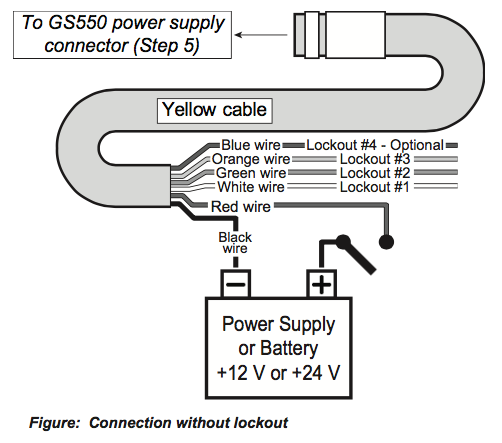
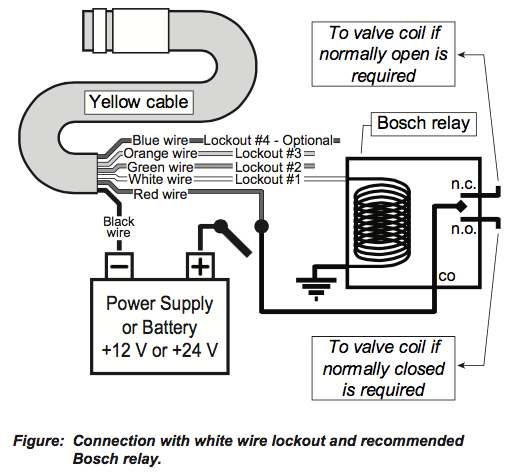
3. Lockout number 1 (if required): connect the white wire to a Bosch relay coil terminal. Connect the other coil terminal of the relay to the ground. When operating properly the white wire will energize at the battery positive level.
Troubleshooting: if no voltage is present on the white wire remove the load connected to the lockout.
Current over 1 ampere on the white wire triggers an auto re-settable fuse. Current flow will resume several seconds after the short circuit is eliminated.
4. Lockout number 2, 3 (if required) and 4 (blue, optional): these wires function in the same way as the white wire described in step 3 above. Each lockout wire can be triggered by a different set of alarm conditions; see the Lockout Settings sub section of this manual.
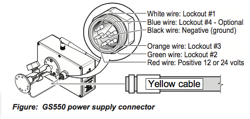
5. Connect the yellow cable to the GS550. The connector is waterproof and well rated for external environments. Simply connect the cable to the display and gently tighten the nut. Do not put a kink in the yellow cable where it enters the connector; any bend in the cable at the base of the connector must not be so severe as to break the internal connections where the cable meets the connector. The power cable requires about 4 1/2 in. behind the display to protect the connector.
2.1d Lockout Settings
Warning, alarm and lockout control is programmed in this menu. The GS550 can be programmed to generate alarms and lockouts for almost all programmed limits and two-block. Furthermore, warnings are generated when approaching programmed load limits and rated capacity (when applicable).
Warning level. When gross load (regardless of tare value) approaches the maximum limit for a load sensor, an intermittent warning message is generated on the LCD. The maximum limit for a load sensor is the lower of a) the operator set limit (Limit Menu) and b) the working load limit (WLL) if rated capacity charts are used. The proportion of a limit that must be reached to trigger the overload warning is the warning level. The default factory setting for the warning level is 90%.
- Go to menu 4G1) WARNING LEVEL.
- Use Up and Down to adjust the warning level.
- Press Next to advance to the alarm level adjustment page or press Menu to confirm any changes and then press Exit three times to return to the operation display
Alarm level. All programmed and rated capacity limits and two-block will generate an audible alarm when the alarm level is reached. Alarms will generate an intermittent alarm message on the LCD. The proportion of a limit that must be reached to trigger an alarm is the alarm level. The default factory setting for the alarm level is 100%
- Go to menu 4G2) ALARM LEVEL.
- Use Up and Down to adjust the alarm level.
- Press Next to advance to the lockout level adjustment page or press Exit three times to return to the operation display
Lockout level. All programmed and rated capacity limits and two-block can generate a lockout signal when the lockout level is reached. By default the lockout wires carry crane power supply voltage as long as the display is in safe condition (to inverse lockout polarity see menu 4G8). When a lockout level is reached voltage is cut on all lockout wires linked to the lockout condition (see menu 4G4 through 4G7). The proportion of a limit that must be reached to trigger lockout is the lockout level. The default factory setting for the lockout level is 105%.
- Go to menu 4G3) LOCKOUT LEVEL.
- Use Up and Down to adjust the lockout level.
- Press Next to advance to the white wire lockout trigger adjustment page or press Exit three times to return to the operation display
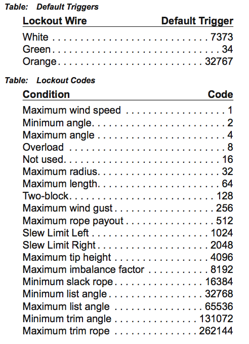
Lockout triggers. During the GS550 wireless crane display installation different events can be programmed to cut voltage on the lockout wires of the yellow cable. Each lockout wire can be linked to a different combination of lockout conditions.
- Go to menu 4G4) WHITE WIRE LOCKOUT TRIGGER
- Select which alarm conditions will trigger lockout on the white wire.
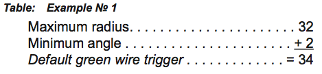
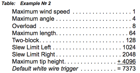
- Add the lockout codes for the selected alarms together to find the lockout trigger number.
- Use Up and Down to adjust the white wire lockout trigger number.
- Press Next to advance to the next wire trigger menu page and repeat steps 2 through 5, or, press Exit three times to return to the operation display.

Lockout relay inversion. By default the lockout wires carry crane power supply voltage as long as the display is in safe condition. When lockout is triggered voltage is cut on the lockout wires linked to the lockout condition.
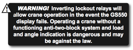
Exceptionally the lockout relay can be inverted so that lockout wires carry no voltage in safe condition and carry crane power supply voltage when in a triggered lockout condition. In this case if the display fails, crane functions will not lockout.
- Go to menu 4G8) LOCKOUT RELAY INVERTED.
- Use Up and Down to switch between“YES”and ”NO”
- Exit three times to return to the operation display.
2.1e Password Settings
Two levels of access are available: administrator and user. The administrator password is required to change the user password. In the event both the administrator and the user passwords are lost please call LSI technical support. Menus accessible from the operation display can be individually protected by the user password.
- Go to menu 4H1) SET ADMINISTRATOR PASSWORD.
- Menu 4H1) SET ADMINISTRATOR PASSWORD: Press Next three times to advance to the set user password page or, to change the administrator password, use Up and Down to adjust the flashing letter and then use Next to advance to the next letter. Press Enter to save any changes.
- Menu 4H2) SET USER PASSWORD: Press Next three times to advance to the tare menu protection page or, to change the user password, use Up and Down to adjust the flashing letter and then use Next to advance to the next letter. Press Enter to save any changes.
- Menu4H3)TARE PROTECTED: use Up and Down to switch between “YES” and “NO” and press Next to advance to the next menu page.
- Repeat step 4 to adjust password protection for each menu as required. Press Enter at any time to save changes made. Press Exit at any time to return to menu 4) INSTALLATION. If there are any unsaved changes the display will request confirmation: press Enter to save before quitting or press Exit to quit without saving.
NEXT SECTION:
(OR USE INDEX TO CLICK ON SECTION NEEDED)
1.1 OVERVIEW
1.2 START-UP
2.1 DISPLAY GS550
2.1a Mounting Bracket
2.1b Antenna Position
2.1c Power Supply and Lockout Connection
2.1d Lockout Settings
2.1e Password Settings
2.3 ANGLE SENSORS FOR THE BOOM OR JIB
2.3a Mounting Procedure
2.3b Angle Calibration Procedure No 1: Mechanical Set-Up
2.3c Angle Calibration Procedure No 2: Correct with the GS550
2.4a Switch Bracket Installation LB011
2.4b GS050 Installation
2.4c GS075B Installation
2.4d Chain length adjustment
2.5a Maximum Boom Extension
2.5b Mounting the Cable Reel
2.5c Boom Length Calibration Procedure No 1: Mechanical Set-Up
2.5d Boom Length Calibration Procedure No 2: Correct with the GS550
2.6a Radius Verification and Adjustment
2.6b Radius Settings
2.6c Basic Radius Parameters for a Lattice Crane
2.6d Basic Radius Parameters for a Telescopic Boom Crane
2.6e Advanced Radius Parameters
2.7 WIRELESS WIND SPEED SENSOR GS020
2.8 WIRELESS LOAD PINS
2.8a LP011, LP015, and LP026
2.8b Load Pin Transmitter GS001
2.9 LINE RIDING TENSIOMETER
2.9a Line Riding Tensiometer Installation
2.9b Line riding tensiometer installation on a swing arm
2.10 LOAD PINS, LINE RIDING TENSIOMETERS AND COMPRESSION CELLS: CALIBRATION
2.11 FOUR POINT LIFT
2.11a Sum Load Indication
2.11b Imbalance
2.11c Slack Rope
2.12 LIST AND TRIM ANGLE SENSOR
2.12a Programming the GS550 for List and Trim Indication
2.12b Mounting Instructions
2.12c List and Trim Angle Calibration Procedure
2.13 ROPE PAYOUT
2.13a Rope Payout Calibration Procedure No 1: Mechanical Set-Up
2.13b Rope Payout Calibration Procedure No 2: Correct with the GS550
2.13c Rope Payout Limits
2.13d Electrical connections
2.14 SLEW SENSOR INSTALLATION
2.14a Encoder Gear Verification
2.14b Slew Encoder Location
2.14c Slew Encoder Orientation
2.14d Slew Encoder Installation
2.14e Slew Transmitter Location
2.14f Slew Transmitter Installation
2.14g Cable Length Adjustment
2.15 SLEW SENSOR CALIBRATION
2.16 DATALOGGER
2.16a Recording Modes
2.16b Date and Time
2.17 SENSOR LIST
2.17a How to Add a Sensor to the GS550
2.17b How to Remove a Sensor from the GS550
2.18 NETWORK OPTIONS
2.18a Listen Only Mode
2.18b Repeater
2.18c Wireless Sensor Update
3. OPERATION
3.1 DISPLAY GS550
3.2 USB PORT
3.3 KEYPAD
3.3a Tare
3.3b Info
3.3c Limit
3.4 DISPLAY ABBREVIATIONS
3.5 SYSTEM MENU
3.5a Menu Numbers
3.5b Menu Navigation
3.5c Password Protection
3.5d Menu Layout
3.5e Parts of Line
3.6 RATED CAPACITY INDICATORS
3.6a Display Programming
3.6b Crane Rigging
3.6c Chart Wizard
3.7 DISPLAY SETTINGS
3.7a Weight Units
3.7b Wind Units
3.7c Language
3.7d Light Intensity
3.7e Contrast
3.7f Backlight Mode
3.8 SYSTEM DIAGNOSTIC
3.8a System Sensors Diagnostic
3.8b Radio Network Diagnostic
3.8c Lockout Diagnostic
3.8d Display Diagnostic
3.8e Digital Input Diagnostic
3.9 WORK AREA MANAGEMENT
3.9a Set Fixed Limits
3.9b Set Dynamic Limits
3.9c Clear all work area limits
3.9d Warning, alarm and lockout
3.9e Slew and work area display
4. USB TOOL
4.1 DATA LOGGER TRANSFER FROM DISPLAY
4.1a Transfer from display to USB device
4.1b Transfer from USB device to PC
4.1c Troubleshooting
4.2 UPLOAD CAPACITY CHARTS
4.3 DATA LOGGER VIEWER
4.3a Installation on a PC
4.3b Quick Start
4.3c Full Report
4.3d Wind Report
5. MAINTENANCE
5.1 SENSORS
5.1a Replacing Sensor Battery
5.2 ANTI-TWO-BLOCK SWITCH
5.2a Replacing the GS050 Batteries
5.2b Replacing the GS075B Battery
5.3 REPLACING A SENSOR ANTENNA
5.4 LOAD CELLS
5.4a Reading Accuracy
5.4b Load Testing
5.4c Care
6. TROUBLESHOOTING
7. CERTIFICATION NOTES
7.1 MODEL NUMBERS
7.2 IMPORTANT NOTES FOR HAZARDOUS AREA CERTIFIED COMPONENTS
7.2a Specifications
7.2b Ensuring Safe Operation in Hazardous Areas
7.2c Product Repair And Servicing
7.3 EQUIPMENT MARKINGS
7.4 GS550 DISPLAY LABELS
7.5 CLASS 1 DIVISION 1 AND DIVISION 2 CERTIFICATIONS
7.6 ATEX CERTIFICATIONS
7.7 FCC AND IC – INSTRUCTIONS TO THE USER
7.8 EMI / EMC
7.9 ENVIRONMENTAL CONDITIONS
7.10 CE
7.10a Declaration of conformity
7.10b CE Safety
8. GS550 MENU OUTLINE
9. LSI PRODUCT LIMITED WARRANTY – 2009/02/16
9.1 LIMITED WARRANTY
9.2 WARRANTYSERVICES PROCEDURES
9.3 EXCLUSION OF OTHER WARRANTIES
9.4 EXCLUSION
9.5 LIMITATION OF LIABILITY
9.6 RECOMMENDED PRACTICES
9.7 CHOICE OF LAW
9.7a Entire Agreement


