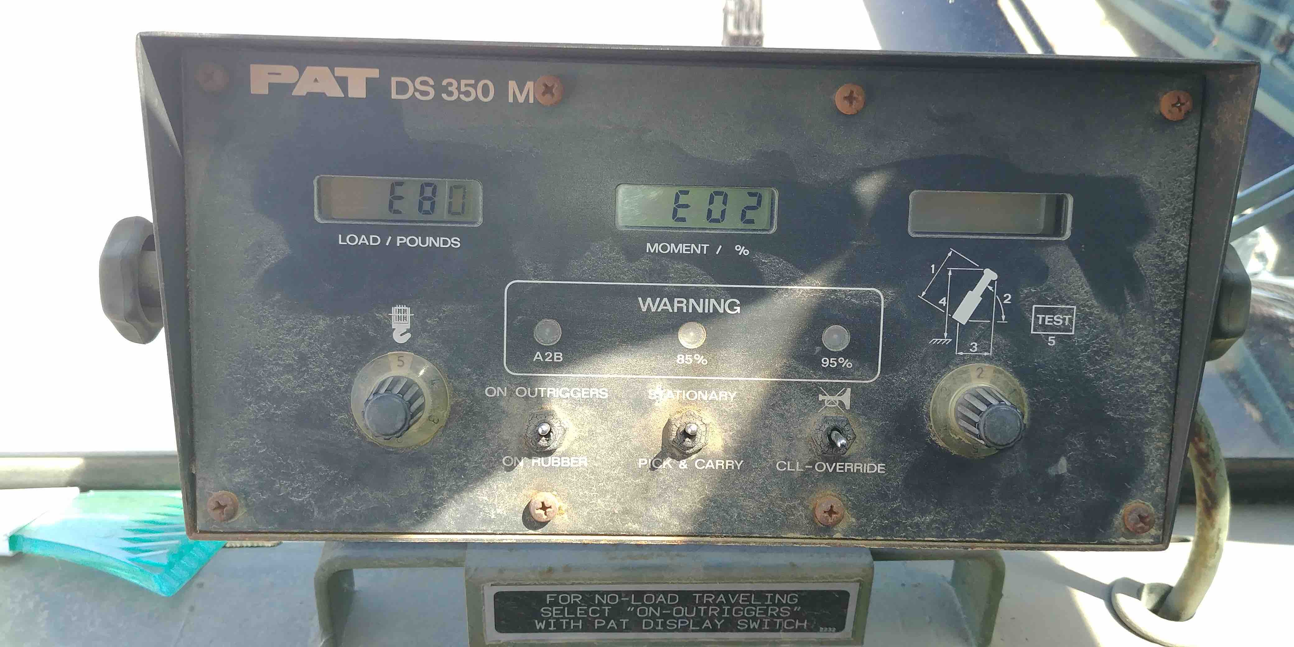
We often get questions regarding and issue that seems to be fairly common or reoccuring. An E85 Error PAT Hirschmann DS350 CPU Module seems to be one of those.
Here is a transcript of a recent email to a customer. If you have an E-85 error, this may help you to troubleshoot the issue.
As always we remain available to help should you need it. Please feel free to call us
—————————-
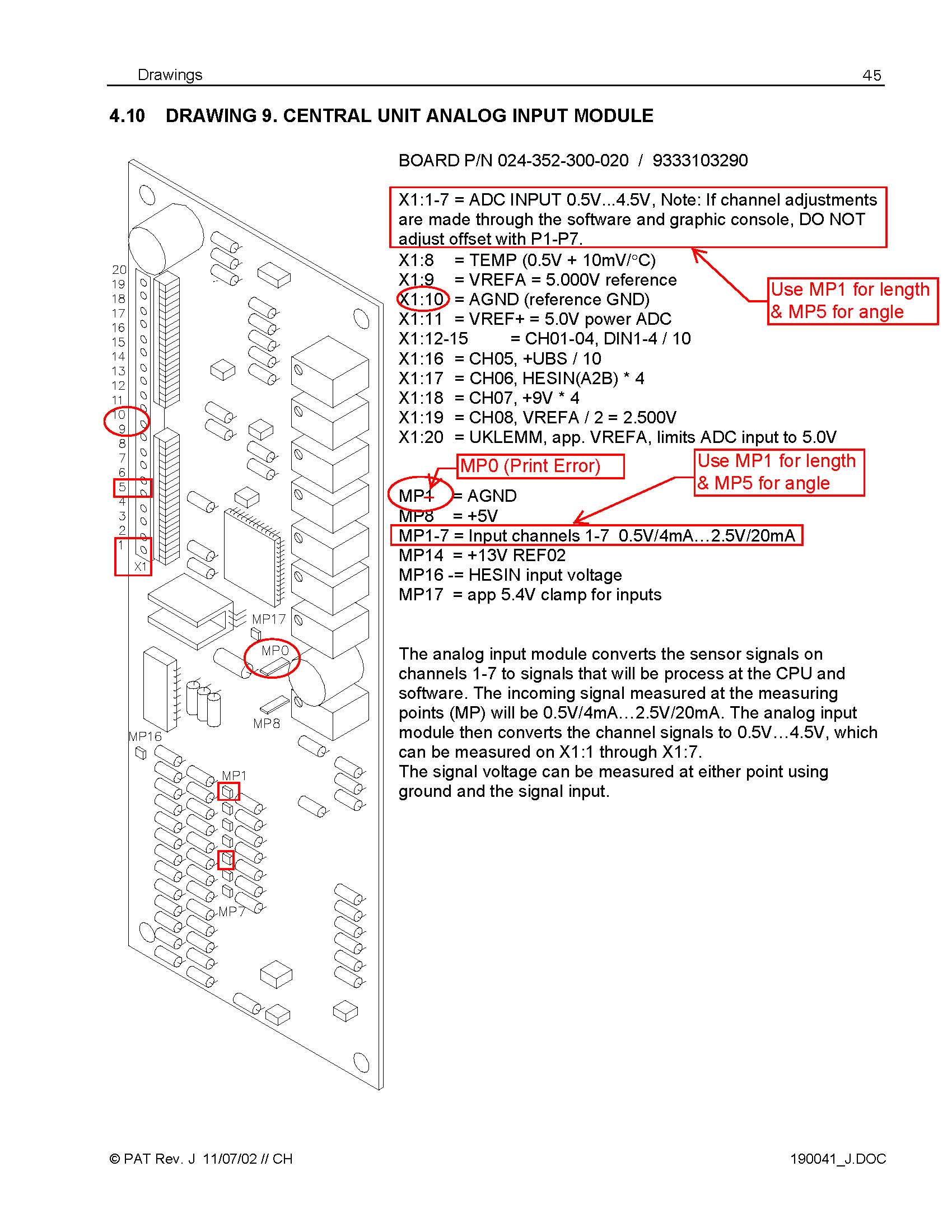
Please refer to images below and the brief test procedure below for the analog input module in the central unit. Remember I previously emailed you the test procedure for all channels when you had trouble with the CPU module in the bus extension and the E2D error. This troubleshooting procedure refers only to two of the relevant channel 1 and 5 on the IO module; main boom length and main boom angle.
Measure the analog input signal from the sensors and the analog output signals to the AD converter at the following test points. Test to be done when the failure E85 is present.
1. Use X1:10 test point as reference GND during measurements (negative of DVM) – AGND test point.
2. Overall boom length – Channel 1:
a. Input on MP1
i. 0.5V with length potentiometer counterclockwise at stop
ii. 2.5V with length potentiometer turned 10 times clockwise at stop
b. Output to ADC converter on X1:1
i. 0.5V with length potentiometer counterclockwise at stop
ii. 4.5V with length potentiometer turned 10 times clockwise at stop
3. Boom Angle – Channel 5:
a. Input on MP1
i. 0.5V with 90 degree boom angle
ii. 2.5V with 0 degree boom angle
iii. 1.5V with 45 degree boom angle (since 90 degree is not measurable)
b. Output to ADC converter on X1:1
i. 0.5V with 90 degree boom angle
ii. 4.5V with 0 degree boom angle
iii. 2.5V with 45 degree boom angle (since 90 degree is not measurable)
4. If 1 to 3 shows no abnormality the following components could create the described E85 failure after a certain time of operation and heat up of components. A heat gun may be used carefully to identify areas of heat sensitivity and for identifying the location. E-Prom module tests or more detailed tests can be performed through our technicians and special test equipment. However a bench test and repair of the central unit is recommended.
a. A/D converter becomes unstable – on analog input board
b. E-Prom Module, or eproms on the module become unstable.
c. Eeprom on E-prom Module lost data.
d. Central Unit CPU becomes unstable
e. System E-Prom has a failure
5. First Recommendation:
a. Check out E-Prom Module – onsite troubleshooting or replacement with new module
b. Replace System Eprom, Data Eprom, TLK Eprom (all plugged into sockets and removable)
c. Alternatively – have Central Unit bench checked and repaired.


